Toyota Camry (XV70): Components
COMPONENTS
ILLUSTRATION
|
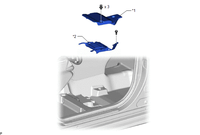
*1 | AUDIO AMPLIFIER COVER |
*2 | STEREO COMPONENT AMPLIFIER ASSEMBLY WITH BRACKET |
ILLUSTRATION

|
*1 | NO. 1 AMPLIFIER BRACKET |
*2 | NO. 2 AMPLIFIER BRACKET |
|
*3 | STEREO COMPONENT AMPLIFIER ASSEMBLY |
- | - |
READ NEXT:
 Removal
REMOVAL CAUTION / NOTICE / HINT
The necessary procedures (adjustment, calibration, initialization, or registration) that must be performed after parts are removed and installed, or replaced during s
Installation
INSTALLATION PROCEDURE 1. INSTALL STEREO COMPONENT AMPLIFIER ASSEMBLY
2. INSTALL NO. 2 AMPLIFIER BRACKET (a) Install the No. 2 amplifier bracket with the 2 screws.
3. INSTALL NO. 1 AMPLIFIER BRACK
Stereo Jack Adapter Assembly
ComponentsCOMPONENTS ILLUSTRATION
*1 LOWER CENTER INSTRUMENT PANEL FINISH PANEL
*2 NO. 1 METER HOOD CLUSTER
*3 NO. 1 STEREO JACK ADAPTER ASSEMBLY
- - RemovalRE
SEE MORE:
Installation
INSTALLATION CAUTION / NOTICE / HINT
HINT:
Use the same procedure for the RH side and LH side.
The following procedure is for the LH side.
PROCEDURE 1. TEMPORARILY INSTALL REAR AXLE CARRIER SUB-ASSEMBLY
(a) Temporarily install the rear axle carrier sub-assembly to the rear shock abso
Air Conditioning Panel
ComponentsCOMPONENTS ILLUSTRATION
*1 AIR CONDITIONING CONTROL ASSEMBLY
*2 NO. 1 METER HOOD CLUSTER
*3 NO. 2 INSTRUMENT PANEL GARNISH SUB-ASSEMBLY
*4 NO. 3 INSTRUMENT PANEL REGISTER ASSEMBLY RemovalREMOVAL PROCEDURE
1. REMOVE NO. 1 METER HOOD CLUSTER Click here
© 2023-2026 Copyright www.tocamry.com
