
Toyota Camry (XV70): Installation
INSTALLATION
PROCEDURE
1. INSTALL CONSOLE BOX ASSEMBLY
(a) Install the console box assembly with the 4 bolts and 2 screws.
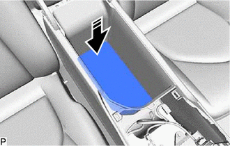
2. INSTALL CONSOLE BOX CARPET
(a) Install the console box carpet as shown in the illustration.
.png) |
Install in this Direction |
3. INSTALL INSTRUMENT PANEL CUP HOLDER
(a) Engage the 2 claws.
(b) Install the instrument panel cup holder with the 3 screws.
4. INSTALL FRONT CONSOLE BOX INSERT SUB-ASSEMBLY
(a) Install the front console box insert sub-assembly with the 5 screws.
5. INSTALL SHIFT POSITION INDICATOR
for UB80E:
Click here
.gif)
for UA80E:
Click here
for UB80F:
Click here
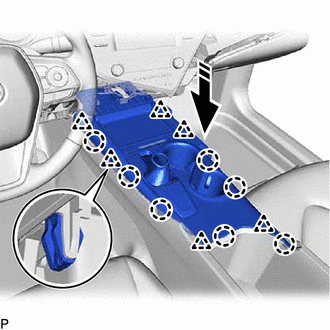
6. INSTALL REAR UPPER CONSOLE PANEL SUB-ASSEMBLY
(a) Connect each connector.
(b) Engage the clamp.
(c) Engage the 6 clips and 7 claws to install the rear upper console panel sub-assembly as shown in the illustration.
|
|
Install in this Direction |
(d) Move the shift lever to P.
7. INSTALL SHIFT LEVER KNOB SUB-ASSEMBLY
for UB80E:
Click here
for UA80E:
Click here
for UB80F:
Click here
8. INSTALL SHIFT LOCK RELEASE BUTTON COVER
for UB80E:
Click here
for UA80E:
Click here
for UB80F:
Click here
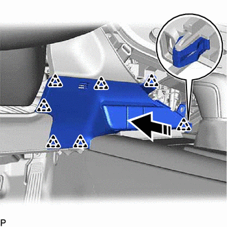
9. INSTALL LOWER CENTER INSTRUMENT PANEL FINISH PANEL
(a) Connect each connector.
(b) Engage the clamp.
(c) Engage the 7 clips to install the lower center instrument panel finish panel as shown in the illustration.
|
|
Install in this Direction |
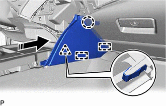
10. INSTALL INSTRUMENT PANEL FINISH PLATE GARNISH
(a) Engage the 2 guides, claw and clip to install the instrument panel finish plate garnish as shown in the illustration.
|
|
Install in this Direction |
11. INSTALL NO. 2 INSTRUMENT PANEL GARNISH SUB-ASSEMBLY
(a) Engage the 11 clips to install the No. 2 instrument panel garnish sub-assembly as shown in the illustration.
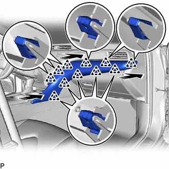
|
|
Install in this Direction |
12. INSTALL NO. 1 METER HOOD CLUSTER
(a) Connect the connector.
(b) Engage the 3 guides and 7 clips to install the No. 1 meter hood cluster as shown in the illustration.
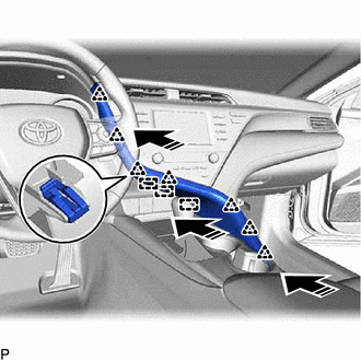
|
|
Install in this Direction |
READ NEXT:
SEE MORE:
 Short to GND in Outer Mirror Indicator(Slave) (C1AB3)
DESCRIPTION This DTC is stored when the blind spot monitor sensor LH detects a short to ground in the outer rear view mirror indicator LH.
DTC No. Detection Item
DTC Detection Condition Trouble Area
C1AB3 Short to GND in Outer Mirror Indicator(Slave) Both of the following
Rocker Panel Moulding
ComponentsCOMPONENTS ILLUSTRATION
*1 FRONT ROCKER PANEL MOULDING END COVER
*2 ROCKER PANEL MOULDING
*3 GROMMET
*4 CLIP
● Non-reusable part
- - RemovalREMOVAL CAUTION / NOTICE / HINT
HINT:
Use the same procedure for the
