
Toyota Camry (XV70): Components
COMPONENTS
ILLUSTRATION
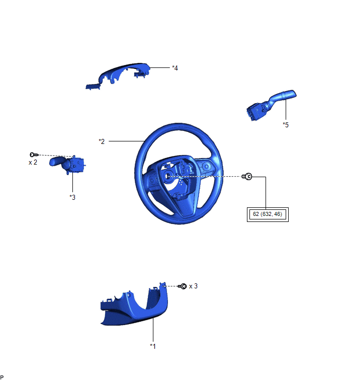
|
*1 | LOWER STEERING COLUMN COVER SUB-ASSEMBLY |
*2 | STEERING WHEEL ASSEMBLY |
|
*3 | TURN SIGNAL SWITCH |
*4 | UPPER STEERING COLUMN COVER |
|
*5 | WINDSHIELD WIPER SWITCH ASSEMBLY |
- | - |
 |
Tightening torque for "Major areas involving basic vehicle performance such as moving/turning/stopping": N*m (kgf*cm, ft.*lbf) |
- | - |
ILLUSTRATION
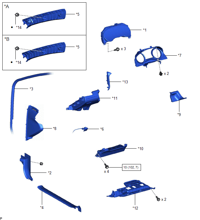
|
*A | w/ Front No. 3 Speaker |
*B | w/o Front No. 3 Speaker |
|
*1 | COMBINATION METER ASSEMBLY |
*2 | COWL SIDE TRIM SUB-ASSEMBLY LH |
|
*3 | FRONT DOOR OPENING TRIM WEATHERSTRIP LH |
*4 | FRONT DOOR SCUFF PLATE LH |
|
*5 | FRONT PILLAR GARNISH LH |
*6 | HOOD LOCK CONTROL LEVER SUB-ASSEMBLY |
|
*7 | INSTRUMENT CLUSTER FINISH PANEL ASSEMBLY |
*8 | INSTRUMENT SIDE PANEL LH |
|
*9 | LOWER INSTRUMENT PANEL FINISH PANEL ASSEMBLY |
*10 | LOWER NO. 1 INSTRUMENT PANEL AIRBAG ASSEMBLY |
|
*11 | NO. 1 INSTRUMENT PANEL SUB-ASSEMBLY |
*12 | NO. 1 INSTRUMENT PANEL UNDER COVER SUB-ASSEMBLY |
|
*13 | NO. 2 METER HOOD CLUSTER |
*14 | CLIP |
 |
N*m (kgf*cm, ft.*lbf): Specified torque |
? | Non-reusable part |
ILLUSTRATION
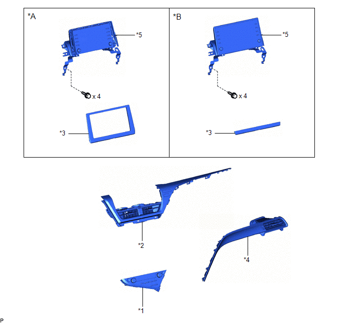
|
*A | for 7 Inch Display |
*B | for 9 Inch Display |
|
*1 | AIR CONDITIONING CONTROL ASSEMBLY |
*2 | CENTER INSTRUMENT CLUSTER FINISH PANEL ASSEMBLY |
|
*3 | CENTER INSTRUMENT CLUSTER FINISH PANEL SUB-ASSEMBLY |
*4 | NO. 3 INSTRUMENT PANEL REGISTER ASSEMBLY |
|
*5 | RADIO AND DISPLAY RECEIVER ASSEMBLY WITH BRACKET |
- | - |
ILLUSTRATION
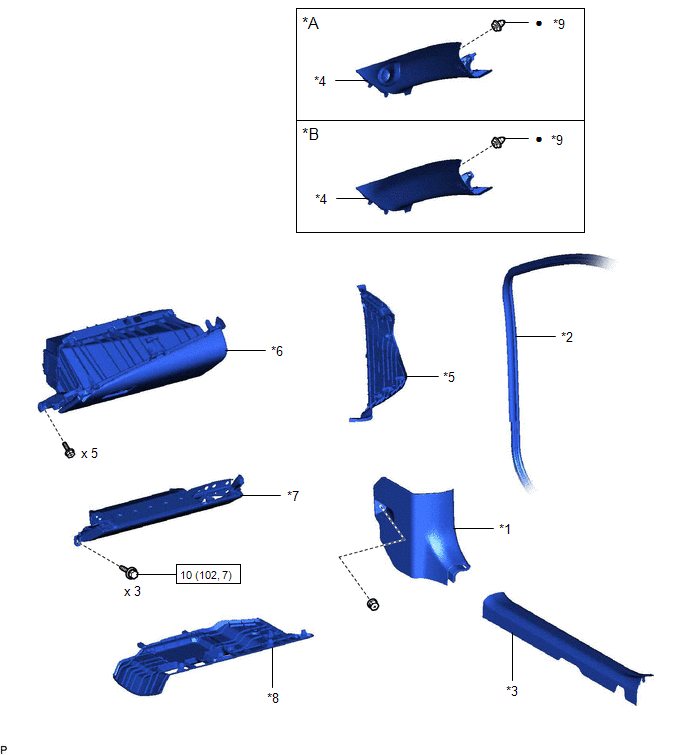
|
*A | w/ Front No. 3 Speaker |
*B | w/o Front No. 3 Speaker |
|
*1 | COWL SIDE TRIM SUB-ASSEMBLY RH |
*2 | FRONT DOOR OPENING TRIM WEATHERSTRIP RH |
|
*3 | FRONT DOOR SCUFF PLATE RH |
*4 | FRONT PILLAR GARNISH RH |
|
*5 | INSTRUMENT SIDE PANEL RH |
*6 | LOWER INSTRUMENT PANEL SUB-ASSEMBLY |
|
*7 | LOWER NO. 2 INSTRUMENT PANEL AIRBAG ASSEMBLY |
*8 | NO. 2 INSTRUMENT PANEL UNDER COVER SUB-ASSEMBLY |
|
*9 | CLIP |
- | - |
|
|
N*m (kgf*cm, ft.*lbf): Specified torque |
? | Non-reusable part |
ILLUSTRATION
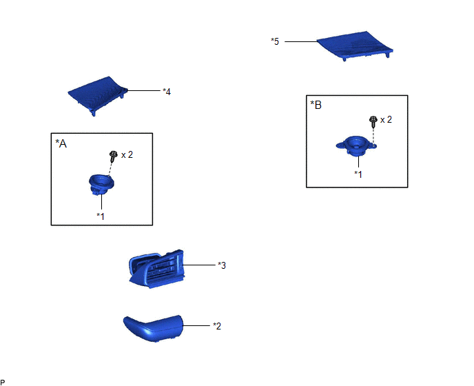
|
*A | for LH Side |
*B | for RH Side |
|
*1 | FRONT NO. 2 SPEAKER ASSEMBLY |
*2 | NO. 1 INSTRUMENT PANEL GARNISH SUB-ASSEMBLY |
|
*3 | NO. 1 INSTRUMENT PANEL REGISTER ASSEMBLY |
*4 | NO. 1 INSTRUMENT PANEL SPEAKER PANEL |
|
*5 | NO. 2 INSTRUMENT PANEL SPEAKER PANEL |
- | - |
ILLUSTRATION
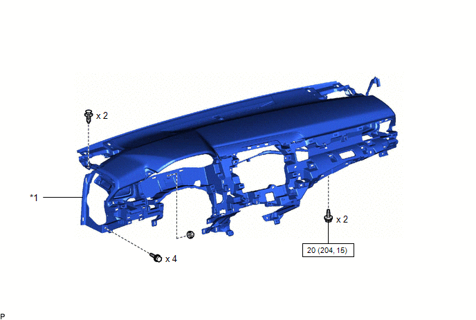
|
*1 | INSTRUMENT PANEL SAFETY PAD SUB-ASSEMBLY |
- | - |
|
|
N*m (kgf*cm, ft.*lbf): Specified torque |
- | - |
ILLUSTRATION
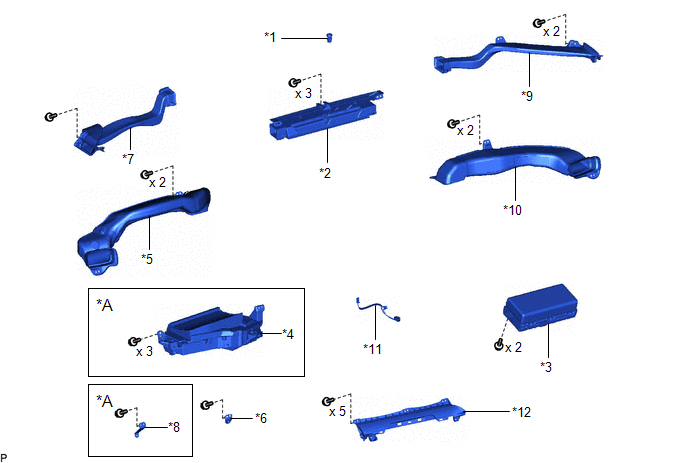
|
*A | w/ Headup Display |
- | - |
|
*1 | AUTOMATIC LIGHT CONTROL SENSOR |
*2 | DEFROSTER NOZZLE ASSEMBLY |
|
*3 | INSTRUMENT PANEL PASSENGER AIRBAG ASSEMBLY |
*4 | METER MIRROR SUB-ASSEMBLY |
|
*5 | NO. 1 HEATER TO REGISTER DUCT SUB-ASSEMBLY |
*6 | NO. 1 METER BRACKET SUB-ASSEMBLY |
|
*7 | NO. 1 SIDE DEFROSTER NOZZLE DUCT |
*8 | NO. 2 METER BRACKET SUB-ASSEMBLY |
|
*9 | NO. 2 SIDE DEFROSTER NOZZLE DUCT |
*10 | NO. 3 HEATER TO REGISTER DUCT SUB-ASSEMBLY |
|
*11 | NO. 3 INSTRUMENT PANEL WIRE |
*12 | RADIO TUNER FINISH RETAINER |
ILLUSTRATION
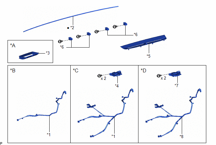
|
*A | w/ Headup Display |
*B | w/o Navigation System |
|
*C | w/ Navigation System |
*D | w/ Manual (SOS) Switch |
|
*1 | ANTENNA CORD SUB-ASSEMBLY |
*2 | INSTRUMENT PANEL CUSHION |
|
*3 | INSTRUMENT PANEL HOLE COVER |
*4 | NAVIGATION ANTENNA ASSEMBLY WITH BRACKET |
|
*5 | NO. 1 DEFROSTER NOZZLE GARNISH |
*6 | NO. 1 INSTRUMENT PANEL PIN |
|
*7 | TELEPHONE AND GPS ANTENNA ASSEMBLY WITH BRACKET |
*8 | TELEPHONE AND GPS ANTENNA CORD |
|
? | Non-reusable part |
- | - |
READ NEXT:
 Removal
REMOVAL CAUTION / NOTICE / HINT
The necessary procedures (adjustment, calibration, initialization or registration) that must be performed after parts are removed and installed, or replaced during ins
Disassembly
DISASSEMBLY PROCEDURE 1. REMOVE INSTRUMENT PANEL PASSENGER AIRBAG ASSEMBLY
Click here 2. REMOVE NO. 1 SIDE DEFROSTER NOZZLE DUCT
(a) Remove the screw <C>.
Remove in this Directi
Reassembly
REASSEMBLY PROCEDURE 1. INSTALL INSTRUMENT PANEL CUSHION
(a) Clean the instrument panel safety pad sub-assembly surface. (1) Remove any remaining double-sided tape from the instrument panel safety pa
SEE MORE:
Removal
REMOVAL CAUTION / NOTICE / HINT
The necessary procedures (adjustment, calibration, initialization or registration) that must be performed after parts are removed and installed, or replaced during roof headlining removal/installation are shown below. Necessary Procedures After Parts Removed/Installe
Parts Location
PARTS LOCATION ILLUSTRATION
*1 INNER REAR VIEW MIRROR ASSEMBLY
- GARAGE DOOR OPENER *2
INSTRUMENT PANEL JUNCTION BLOCK ASSEMBLY - ECU-DCC NO. 2 FUSE
- ECU-IG1 NO. 3 FUSE
