
Toyota Camry (XV70): Disassembly
DISASSEMBLY
PROCEDURE
1. REMOVE INSTRUMENT PANEL PASSENGER AIRBAG ASSEMBLY
Click here .gif)
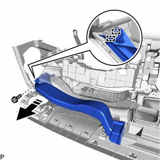
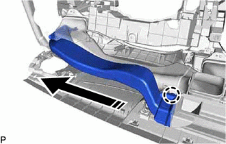
2. REMOVE NO. 1 SIDE DEFROSTER NOZZLE DUCT
(a) Remove the screw <C>.
.png) |
Remove in this Direction |
(b) Disengage the 2 guides as shown in the illustration.
(c) Disengage the claw to remove the No. 1 side defroster nozzle duct as shown in the illustration.
|
|
Remove in this Direction |
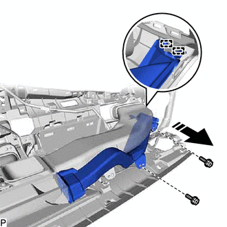
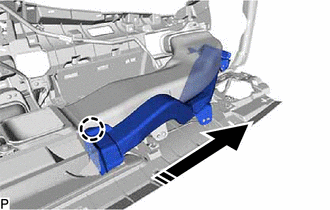
3. REMOVE NO. 2 SIDE DEFROSTER NOZZLE DUCT
(a) Remove the 2 screws <C>.
|
|
Remove in this Direction |
(b) Disengage the 2 guides as shown in the illustration.
(c) Disengage the claw to remove the No. 2 side defroster nozzle duct as shown in the illustration.
|
|
Remove in this Direction |
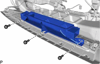
4. REMOVE DEFROSTER NOZZLE ASSEMBLY
| (a) Remove the 3 screws <C> and defroster nozzle assembly. |
|
5. REMOVE METER MIRROR SUB-ASSEMBLY (w/ Headup Display)
Click here
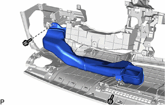
6. REMOVE NO. 1 HEATER TO REGISTER DUCT SUB-ASSEMBLY
| (a) Remove the 2 screws <C> and No. 1 heater to register duct sub-assembly. |
|
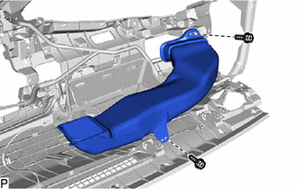
7. REMOVE NO. 3 HEATER TO REGISTER DUCT SUB-ASSEMBLY
| (a) Remove the 2 screws <C> and No. 3 heater to register duct sub-assembly. |
|
8. REMOVE ANTENNA CORD SUB-ASSEMBLY (w/o Navigation System)
Click here
9. REMOVE ANTENNA CORD SUB-ASSEMBLY (w/ Navigation System)
Click here
10. REMOVE NAVIGATION ANTENNA ASSEMBLY WITH BRACKET (w/ Navigation System)
Click here
11. REMOVE TELEPHONE AND GPS ANTENNA CORD (w/ Manual (SOS) Switch)
Click here
12. REMOVE TELEPHONE AND GPS ANTENNA ASSEMBLY WITH BRACKET (w/ Manual (SOS) Switch)
Click here
13. REMOVE AUTOMATIC LIGHT CONTROL SENSOR
Click here
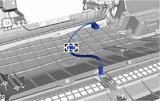
14. REMOVE NO. 3 INSTRUMENT PANEL WIRE
| (a) Disengage the clamp to remove the No. 3 instrument panel wire. |
|
15. REMOVE RADIO TUNER FINISH RETAINER
| (a) Remove the 5 screws <C> and radio tuner finish retainer. |
|
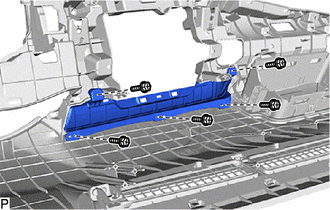
16. REMOVE NO. 1 METER BRACKET SUB-ASSEMBLY
| (a) Remove the screw <C> and No. 1 meter bracket sub-assembly. |
|
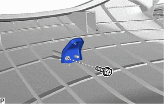
17. REMOVE NO. 2 METER BRACKET SUB-ASSEMBLY (w/ Headup Display)
| (a) Remove the screw <C> and No. 2 meter bracket sub-assembly. |
|
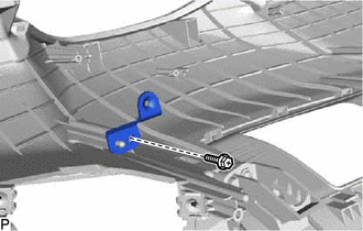
18. REMOVE NO. 1 DEFROSTER NOZZLE GARNISH
(a) Disengage the 4 clips.
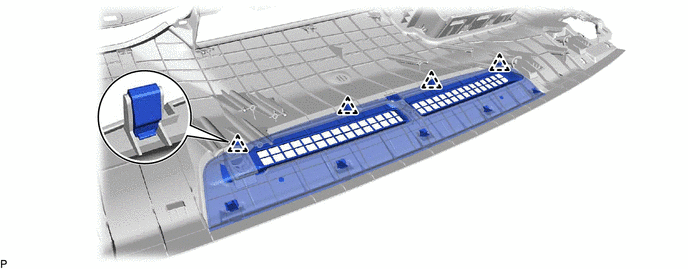
(b) Disengage the 5 guides to remove the No. 1 defroster nozzle garnish.
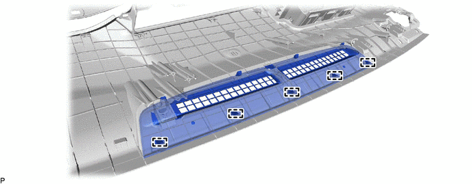
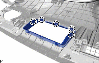
19. REMOVE INSTRUMENT PANEL HOLE COVER (w/ Headup Display)
| (a) Disengage the 5 claws. |
|
| (b) Disengage the 3 guides to remove the instrument panel hole cover. |
|
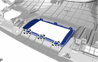
20. REMOVE NO. 1 INSTRUMENT PANEL PIN
| (a) Remove the 4 screws <C> and 4 No. 1 instrument panel pins. |
|
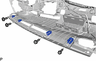
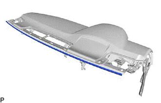
21. REMOVE INSTRUMENT PANEL CUSHION
| (a) Remove the instrument panel cushion. |
|
READ NEXT:
SEE MORE:
 Components
COMPONENTS ILLUSTRATION
*A for A25A-FKS
- -
*1 NO. 1 VACUUM HOSE CONNECTOR
*2 UNION TO CHECK VALVE HOSE
*3 VACUUM HOSE
*4 CLIP ILLUSTRATION
*A for 2GR-FKS
- -
*1 FRONT CENTER UPPER SUSPENSION BRACE SUB-ASSEMBLY
Cooling Fan Circuit
DESCRIPTION The ECM calculates an appropriate cooling fan speed based on the engine coolant temperature, air conditioning switch status, refrigerant pressure, engine speed and vehicle speed, and sends a signal to the cooling fan ECU (fan with motor assembly). The cooling fan ECU (fan with motor asse
