
Toyota Camry (XV70): Reassembly
REASSEMBLY
PROCEDURE
1. INSTALL INSTRUMENT PANEL CUSHION
(a) Clean the instrument panel safety pad sub-assembly surface.
(1) Remove any remaining double-sided tape from the instrument panel safety pad sub-assembly.
(2) Wipe off any tape adhesive residue with cleaner.
(b) Remove the release paper from a new instrument panel cushion.
HINT:
After removing the release paper, keep the exposed adhesive free from foreign matter.
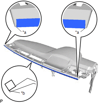
| (c) Install the instrument panel cushion as shown in the illustration. |
|
2. INSTALL NO. 1 INSTRUMENT PANEL PIN
| (a) Install the 4 No. 1 instrument panel pins with the 4 screws <C>. |
|
.png)
3. INSTALL INSTRUMENT PANEL HOLE COVER (w/ Headup Display)
| (a) Engage the 3 guides. |
|
.png)
| (b) Engage the 5 claws to install the instrument panel hole cover. |
|
.png)
4. INSTALL NO. 1 DEFROSTER NOZZLE GARNISH
(a) Engage the 5 guides.
.png)
(b) Engage the 4 clips to install the No. 1 defroster nozzle garnish.
.png)
5. INSTALL NO. 2 METER BRACKET SUB-ASSEMBLY (w/ Headup Display)
| (a) Install the No. 2 meter bracket sub-assembly with the screw <C>. |
|
.png)
6. INSTALL NO. 1 METER BRACKET SUB-ASSEMBLY
| (a) Install the No. 1 meter bracket sub-assembly with the screw <C>. |
|
.png)
7. INSTALL RADIO TUNER FINISH RETAINER
| (a) Install the radio tuner finish retainer with the 5 screws <C>. |
|
.png)
8. INSTALL NO. 3 INSTRUMENT PANEL WIRE
| (a) Engage the clamp to install the No. 3 instrument panel wire. |
|
.png)
9. INSTALL AUTOMATIC LIGHT CONTROL SENSOR
Click here
.gif)
10. INSTALL ANTENNA CORD SUB-ASSEMBLY (w/o Navigation System)
Click here
11. INSTALL NAVIGATION ANTENNA ASSEMBLY WITH BRACKET (w/ Navigation System)
Click here
12. INSTALL ANTENNA CORD SUB-ASSEMBLY (w/ Navigation System)
Click here
13. INSTALL TELEPHONE AND GPS ANTENNA ASSEMBLY WITH BRACKET (w/ Manual (SOS) Switch)
Click here
14. INSTALL TELEPHONE AND GPS ANTENNA CORD (w/ Manual (SOS) Switch)
Click here
15. INSTALL NO. 3 HEATER TO REGISTER DUCT SUB-ASSEMBLY
| (a) Install the No. 3 heater to register duct sub-assembly with the 2 screws <C>. |
|
.png)
16. INSTALL NO. 1 HEATER TO REGISTER DUCT SUB-ASSEMBLY
| (a) Install the No. 1 heater to register duct sub-assembly with the 2 screws <C>. |
|
.png)
17. INSTALL METER MIRROR SUB-ASSEMBLY (w/ Headup Display)
Click here
18. INSTALL DEFROSTER NOZZLE ASSEMBLY
| (a) Install the defroster nozzle assembly with the 3 screws <C>. |
|
.png)
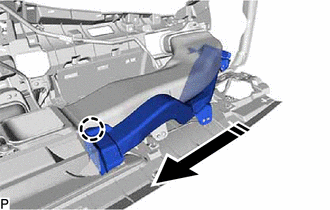
19. INSTALL NO. 2 SIDE DEFROSTER NOZZLE DUCT
(a) Engage the claw as shown in the illustration.
.png) |
Install in this Direction |
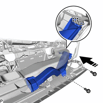
(b) Engage the 2 guides as shown in the illustration.
|
|
Install in this Direction |
(c) Install the No. 2 side defroster nozzle duct with the 2 screws <C>.
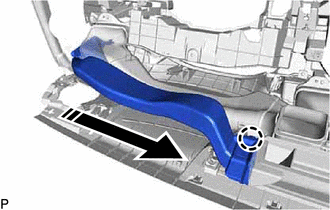
20. INSTALL NO. 1 SIDE DEFROSTER NOZZLE DUCT
(a) Engage the claw as shown in the illustration.
|
|
Install in this Direction |
(b) Engage the 2 guides as shown in the illustration.
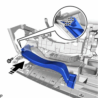
|
|
Install in this Direction |
(c) Install the No. 1 side defroster nozzle duct with the screw <C>.
21. INSTALL INSTRUMENT PANEL PASSENGER AIRBAG ASSEMBLY
Click here
READ NEXT:
SEE MORE:
 Components
COMPONENTS ILLUSTRATION
*1 CLEARANCE WARNING ECU ASSEMBLY
*2 ECU INTEGRATION BOX RH
*3 LOWER INSTRUMENT PANEL SUB-ASSEMBLY
- -
N*m (kgf*cm, ft.*lbf): Specified torque
- -
Components
COMPONENTS ILLUSTRATION
*1 COWL SIDE TRIM SUB-ASSEMBLY LH
*2 FRONT DOOR OPENING TRIM WEATHERSTRIP LH
*3 FRONT DOOR SCUFF PLATE LH
*4 HOOD LOCK CONTROL LEVER SUB-ASSEMBLY
*5 INSTRUMENT SIDE PANEL LH
*6 NO. 1 INSTRUMENT PANEL SUB-ASSEMBLY
