
Toyota Camry (XV70): Installation
INSTALLATION
PROCEDURE
1. INSTALL INSTRUMENT PANEL SAFETY PAD SUB-ASSEMBLY
(a) When installing a new instrument panel safety pad sub-assembly:
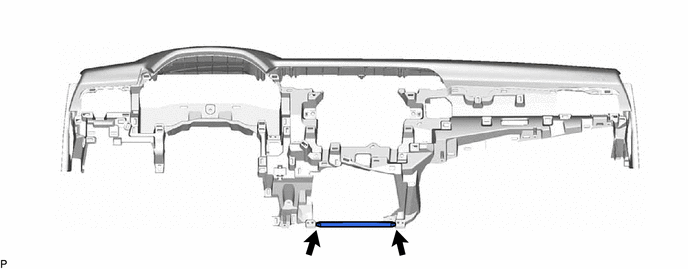
(1) Immediately before installing the instrument panel safety pad sub-assembly, twist and cut off the portion as shown in the illustration.
(b) Engage the 4 guides to temporarily install the instrument panel safety pad sub-assembly as shown in the illustration.
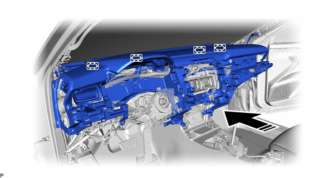
.png) |
Install in this Direction |
- | - |
NOTICE:
- Do not damage the instrument panel safety pad sub-assembly.
- Do not allow the wire harnesses to interfere with the surrounding parts.
(c) Install the instrument panel safety pad sub-assembly with the 4 bolts <B>, 2 bolts <A> and nut <E>.
.png)
|
*a | Bolt <A> |
*b | Bolt <B> |
|
*c | Clip |
*d | Nut <E> |
Torque:
Bolt <A> :
20 N·m {204 kgf·cm, 15 ft·lbf}
(d) Install the 2 clips.
(e) Engage each clamp.
.png)
|
*A | w/ Headup Display |
*B | w/ Navigation System |
|
*C | w/ Manual (SOS) Switch |
- | - |
(f) Connect each connector.
(g) Engage the 2 claws to connect the cooler (room temp. sensor) thermistor as shown in the illustration.
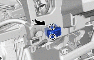
|
|
Install in this Direction |
2. CONNECT NO. 5 INSTRUMENT PANEL WIRE
Click here .gif)
3. INSTALL NO. 1 INSTRUMENT PANEL REGISTER ASSEMBLY
(a) Engage the 2 clips and 2 claws to install the No. 1 instrument panel register assembly as shown in the illustration.
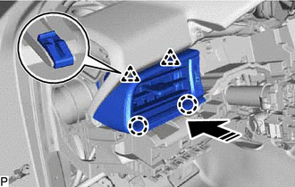
|
|
Install in this Direction |
4. INSTALL NO. 1 INSTRUMENT PANEL GARNISH SUB-ASSEMBLY
(a) Engage the 4 clips to install the No. 1 instrument panel garnish sub-assembly as shown in the illustration.
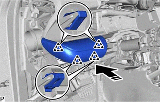
|
|
Install in this Direction |
5. INSTALL FRONT NO. 2 SPEAKER ASSEMBLY (for RH Side)
HINT:
Use the same procedure as for the LH side.
Click here
6. INSTALL NO. 2 INSTRUMENT PANEL SPEAKER PANEL
(a) Engage the 2 guides as shown in the illustration.
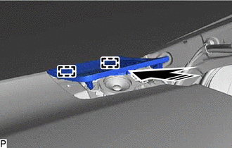
|
|
Install in this Direction |
(b) Engage the 2 clips to install the No. 2 instrument panel speaker panel as shown in the illustration.
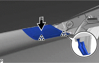
|
|
Install in this Direction |
7. INSTALL FRONT NO. 2 SPEAKER ASSEMBLY (for LH Side)
Click here
8. INSTALL NO. 1 INSTRUMENT PANEL SPEAKER PANEL
(a) Engage the 2 guides as shown in the illustration.
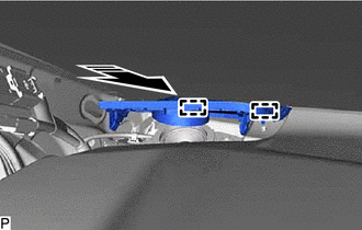
|
|
Install in this Direction |
(b) Engage the 2 clips to install the No. 1 instrument panel speaker panel as shown in the illustration.
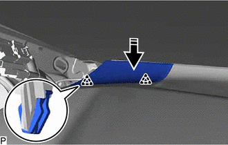
|
|
Install in this Direction |
9. INSTALL LOWER INSTRUMENT PANEL SUB-ASSEMBLY
(a) Connect the connector.
(b) Engage the 4 claws as shown in the illustration.
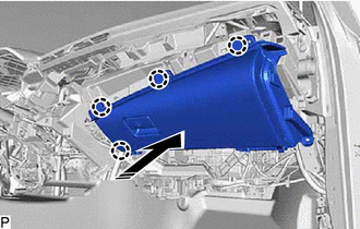
|
|
Install in this Direction |
(c) Install the lower instrument panel sub-assembly with the 5 screws <C>.
10. INSTALL LOWER NO. 2 INSTRUMENT PANEL AIRBAG ASSEMBLY
Click here
11. INSTALL NO. 2 INSTRUMENT PANEL UNDER COVER SUB-ASSEMBLY
(a) Connect the connector.
(b) Engage the clamp.
(c) Engage the 2 guides as shown in the illustration.
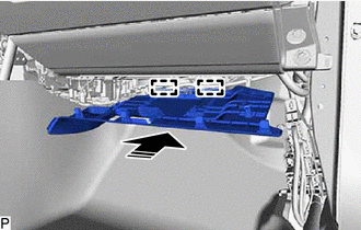
|
|
Install in this Direction |
(d) Engage the 4 claws to install the No. 2 instrument panel under cover sub-assembly as shown in the illustration.
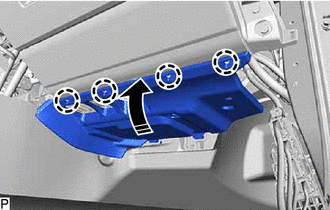
|
|
Install in this Direction |
12. INSTALL INSTRUMENT SIDE PANEL RH
(a) Engage the 3 guides as shown in the illustration.
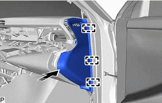
|
|
Install in this Direction |
(b) Engage the 4 clips and 2 claws to install the instrument side panel RH as shown in the illustration.
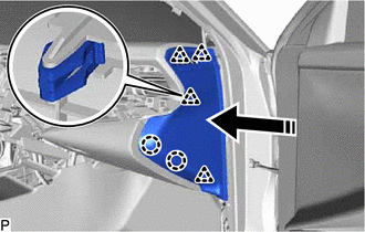
|
|
Install in this Direction |
13. INSTALL FRONT PILLAR GARNISH RH
HINT:
Use the same procedure as for the LH side.
Click here
14. INSTALL FRONT DOOR OPENING TRIM WEATHERSTRIP RH
Click here
15. INSTALL COWL SIDE TRIM SUB-ASSEMBLY RH
HINT:
Use the same procedure as for the LH side.
Click here
16. INSTALL FRONT DOOR SCUFF PLATE RH
HINT:
Use the same procedure as for the LH side.
Click here
17. INSTALL RADIO AND DISPLAY RECEIVER ASSEMBLY WITH BRACKET (for 7 Inch Display)
Click here
18. INSTALL RADIO AND DISPLAY RECEIVER ASSEMBLY WITH BRACKET (for 9 Inch Display)
Click here
19. INSTALL CENTER INSTRUMENT CLUSTER FINISH PANEL ASSEMBLY
(a) Connect each connector.
(b) Engage the 2 claws and 4 clips as shown in the illustration.
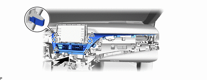
|
|
Install in this Direction |
- | - |
(c) Engage the 4 clips in the order shown in the illustration to install the center instrument cluster finish panel assembly.
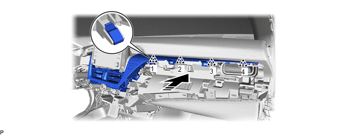
|
|
Install in this Direction |
- | - |
20. INSTALL CENTER INSTRUMENT CLUSTER FINISH PANEL SUB-ASSEMBLY (for 7 Inch Display)
(a) Engage the 4 claws and 7 clips to install the center instrument cluster finish panel sub-assembly as shown in the illustration.
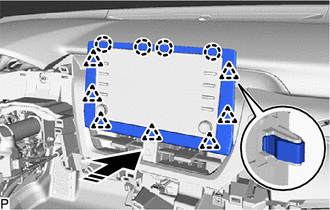
|
|
Install in this Direction |
21. INSTALL CENTER INSTRUMENT CLUSTER FINISH PANEL SUB-ASSEMBLY (for 9 Inch Display)
(a) Engage the 3 clips to install the center instrument cluster finish panel sub-assembly as shown in the illustration.
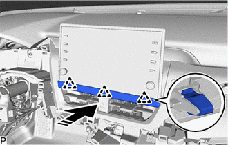
|
|
Install in this Direction |
22. INSTALL AIR CONDITIONING CONTROL ASSEMBLY
Click here
23. INSTALL NO. 3 INSTRUMENT PANEL REGISTER ASSEMBLY
(a) w/ Illumination:
(1) Connect the connector.
(b) Engage the 11 clips to install the No. 3 instrument panel register assembly as shown in the illustration.
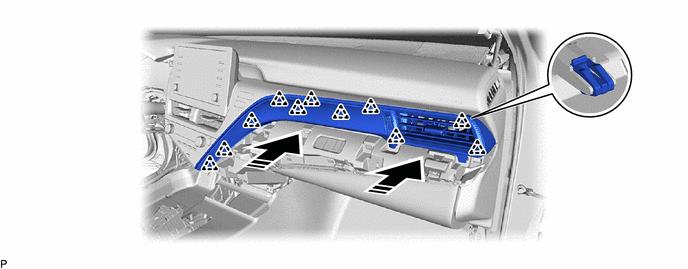
|
|
Install in this Direction |
- | - |
24. INSTALL LOWER INSTRUMENT PANEL FINISH PANEL ASSEMBLY
(a) w/ Smart Key System:
(1) Connect the connector.
(b) Engage the 4 clips to install the lower instrument panel finish panel assembly as shown in the illustration.
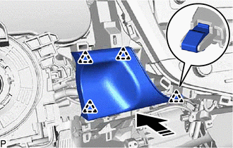
|
|
Install in this Direction |
25. INSTALL COMBINATION METER ASSEMBLY
Click here
26. INSTALL INSTRUMENT CLUSTER FINISH PANEL ASSEMBLY
(a) Connect the connector.
(b) Engage the 2 guides and 4 clips to install the instrument cluster finish panel assembly as shown in the illustration.
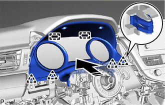
|
|
Install in this Direction |
(c) Install the 2 clips.
27. INSTALL LOWER NO. 1 INSTRUMENT PANEL AIRBAG ASSEMBLY
Click here
28. INSTALL NO. 1 INSTRUMENT PANEL SUB-ASSEMBLY
(a) Connect each connector.
(b) Engage the clamp.
(c) Engage the 6 clips to install the No. 1 instrument panel sub-assembly as shown in the illustration.
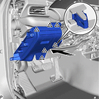
|
|
Install in this Direction |
29. CONNECT HOOD LOCK CONTROL LEVER SUB-ASSEMBLY
(a) Engage the claw and 2 guides to connect the hood lock control lever sub-assembly.
30. INSTALL NO. 2 METER HOOD CLUSTER
(a) Engage the 3 clips to install the No. 2 meter hood cluster as shown in the illustration.
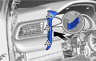
|
|
Install in this Direction |
31. INSTALL NO. 1 INSTRUMENT PANEL UNDER COVER SUB-ASSEMBLY
(a) Engage the 2 claws to connect the DLC3 connector.
(b) Engage the 2 clamps.
(c) Connect the connector.
(d) Engage the guide as shown in the illustration.
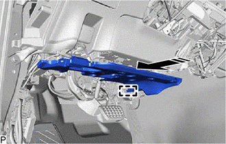
|
|
Install in this Direction |
(e) Engage the 3 claws as shown in the illustration.
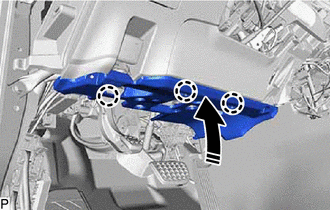
|
|
Install in this Direction |
(f) Install the No. 1 instrument panel under cover sub-assembly with the 2 screws <C>.
32. INSTALL INSTRUMENT SIDE PANEL LH
(a) Engage the 3 guides as shown in the illustration.
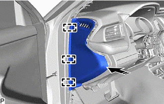
|
|
Install in this Direction |
(b) Engage the 4 clips and 2 claws to install the instrument side panel LH as shown in the illustration.
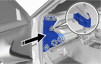
|
|
Install in this Direction |
33. INSTALL FRONT PILLAR GARNISH LH
Click here
34. INSTALL FRONT DOOR OPENING TRIM WEATHERSTRIP LH
Click here
35. INSTALL COWL SIDE TRIM SUB-ASSEMBLY LH
Click here
36. INSTALL FRONT DOOR SCUFF PLATE LH
Click here
37. INSTALL CONSOLE BOX ASSEMBLY
Click here
38. INSTALL TURN SIGNAL SWITCH
Click here
39. INSTALL WINDSHIELD WIPER SWITCH ASSEMBLY
Click here
40. INSTALL UPPER STEERING COLUMN COVER
Click here
41. INSTALL LOWER STEERING COLUMN COVER SUB-ASSEMBLY
Click here
42. ALIGN FRONT WHEELS FACING STRAIGHT AHEAD
43. INSPECT AND ADJUST SPIRAL CABLE WITH SENSOR SUB-ASSEMBLY
Click here
44. INSTALL STEERING WHEEL ASSEMBLY
Click here
45. CHECK STEERING WHEEL CENTER POINT
46. INSTALL HORN BUTTON ASSEMBLY
Click here
READ NEXT:
SEE MORE:
 Diagnostic Trouble Code Chart
DIAGNOSTIC TROUBLE CODE CHART Road Sign Assist System
DTC No. Detection Item
Link U010087
Lost Communication with ECM/PCM "A" Missing Message
U012587 Lost Communication with Multi-axis Acceleration Sensor Module Missing Message
U012987 Los
Right Rear Wheel Speed Sensor Supply Voltage Circuit Short to Ground or Open (C14E914)
DESCRIPTION Refer to DTC C051212 Click here
DTC No. Detection Item
DTC Detection Condition Trouble Area
C14E914 Right Rear Wheel Speed Sensor Supply Voltage Circuit Short to Ground or Open
An open or short in the speed sensor power supply circuit is detected for 0.
