
Toyota Camry (XV70): Removal
REMOVAL
CAUTION / NOTICE / HINT
The necessary procedures (adjustment, calibration, initialization or registration) that must be performed after parts are removed and installed, or replaced during instrument panel safety pad sub-assembly removal/installation are shown below.
Necessary Procedures After Parts Removed/Installed/Replaced|
Replaced Part or Performed Procedure |
Necessary Procedure | Effect/Inoperative Function when Necessary Procedure not Performed |
Link |
|---|---|---|---|
|
Disconnect cable from negative battery terminal |
Perform steering sensor zero point calibration |
Lane Tracing Assist System |
|
|
Pre-collision System | |||
|
Memorize steering angle neutral point |
Parking Assist Monitor System |
| |
|
Panoramic View Monitor System |
|
CAUTION:
Some of these service operations affect the SRS airbag system. Read the precautionary notices concerning the SRS airbag system before servicing.
.png)
Click here
.gif)
PROCEDURE
1. PRECAUTION
Click here
NOTICE:
After turning the engine switch off, waiting time may be required before disconnecting the cable from the negative (-) battery terminal. Therefore, make sure to read the disconnecting the cable from the negative (-) battery terminal notices before proceeding with work.
2. ALIGN FRONT WHEELS FACING STRAIGHT AHEAD
3. REMOVE HORN BUTTON ASSEMBLY
Click here
4. REMOVE STEERING WHEEL ASSEMBLY
Click here
5. REMOVE LOWER STEERING COLUMN COVER SUB-ASSEMBLY
Click here
6. REMOVE UPPER STEERING COLUMN COVER
Click here
7. REMOVE WINDSHIELD WIPER SWITCH ASSEMBLY
Click here
8. REMOVE TURN SIGNAL SWITCH
Click here
9. REMOVE CONSOLE BOX ASSEMBLY
Click here
10. REMOVE FRONT DOOR SCUFF PLATE LH
Click here
11. REMOVE COWL SIDE TRIM SUB-ASSEMBLY LH
Click here
12. DISCONNECT FRONT DOOR OPENING TRIM WEATHERSTRIP LH
(a) Disconnect the front door opening trim weatherstrip LH.
13. REMOVE FRONT PILLAR GARNISH LH
Click here
14. REMOVE INSTRUMENT SIDE PANEL LH
(a) Apply protective tape to the area shown in the illustration.
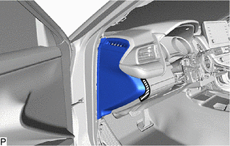
.png) |
Protective Tape |
(b) Using a moulding remover, disengage the 2 claws and 4 clips as shown in the illustration.
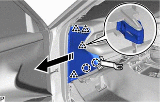
.png) |
Remove in this Direction |
NOTICE:
To prevent damage to the instrument side panel LH, do not insert the moulding remover in a position other than shown in the illustration.
(c) Disengage the 3 guides to remove the instrument side panel LH as shown in the illustration.
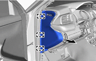
|
|
Remove in this Direction |
15. REMOVE NO. 1 INSTRUMENT PANEL UNDER COVER SUB-ASSEMBLY
| (a) Remove the 2 screws <C>. |
|
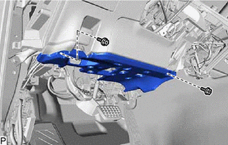
(b) Disengage the 3 claws as shown in the illustration.
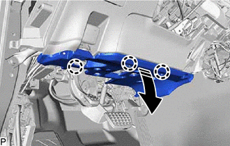
|
|
Remove in this Direction |
(c) Disengage the guide as shown in the illustration.
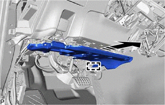
|
|
Remove in this Direction |
(d) Disconnect the connector.
| (e) Disengage the 2 claws to disconnect the DLC3 connector. |
|
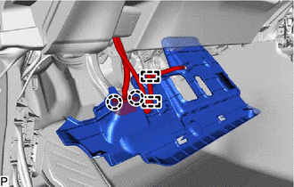
(f) Disengage the 2 clamps to remove the No. 1 instrument panel under cover sub-assembly.
16. REMOVE NO. 2 METER HOOD CLUSTER
(a) Disengage the 3 clips to remove the No. 2 meter hood cluster as shown in the illustration.
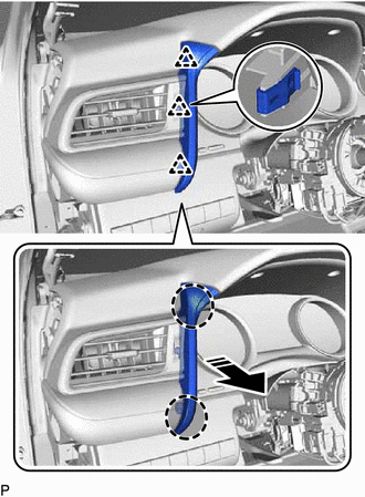
.png) |
Place Hand Here |
|
|
Remove in this Direction |
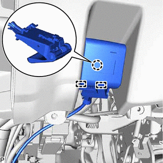
17. DISCONNECT HOOD LOCK CONTROL LEVER SUB-ASSEMBLY
| (a) Disengage the claw and 2 guides to disconnect the hood lock control lever sub-assembly. |
|
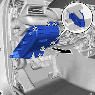
18. REMOVE NO. 1 INSTRUMENT PANEL SUB-ASSEMBLY
(a) Disengage the 6 clips as shown in the illustration.
|
|
Remove in this Direction |
(b) Disengage the clamp.
(c) Disconnect each connector to remove the No. 1 instrument panel sub-assembly.
19. REMOVE LOWER NO. 1 INSTRUMENT PANEL AIRBAG ASSEMBLY
Click here
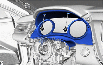
20. REMOVE INSTRUMENT CLUSTER FINISH PANEL ASSEMBLY
| (a) Remove the 2 clips. |
|
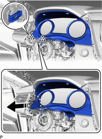
(b) Disengage the 2 clips as shown in the illustration.
|
|
Place Hand Here |
|
|
Remove in this Direction |
(c) Disengage the 2 clips as shown in the illustration.
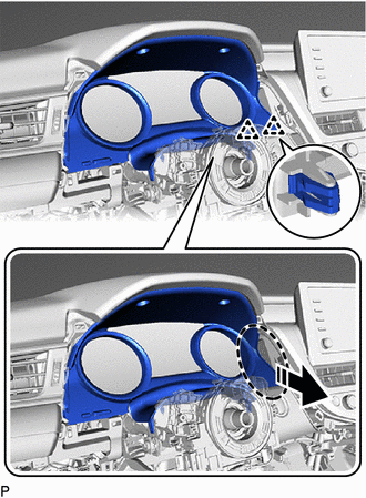
|
|
Place Hand Here |
|
|
Remove in this Direction |
(d) Disengage the 2 guides as shown in the illustration.
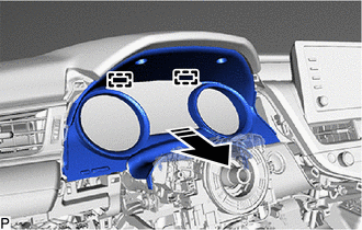
|
|
Remove in this Direction |
(e) Disconnect the connector to remove the instrument cluster finish panel assembly.
21. REMOVE COMBINATION METER ASSEMBLY
Click here
22. REMOVE LOWER INSTRUMENT PANEL FINISH PANEL ASSEMBLY
(a) Disengage the 4 clips to remove the lower instrument panel finish panel assembly as shown in the illustration.
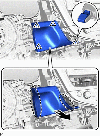
|
|
Place Hand Here |
|
|
Remove in this Direction |
(b) w/ Smart Key System:
(1) Disconnect the connector.
23. REMOVE NO. 3 INSTRUMENT PANEL REGISTER ASSEMBLY
(a) Disengage the 8 clips in the order shown in the illustration.
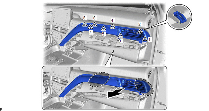
|
|
Place Hand Here |
|
Remove in this Direction |
(b) Disengage the 3 clips in the order shown in the illustration to remove the No. 3 instrument panel register assembly.
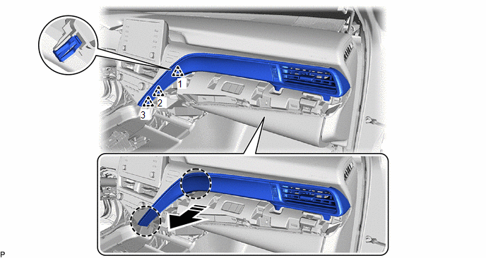
|
|
Place Hand Here |
|
Remove in this Direction |
(c) w/ Illumination:
(1) Disconnect the connector.
24. REMOVE AIR CONDITIONING CONTROL ASSEMBLY
Click here
25. REMOVE CENTER INSTRUMENT CLUSTER FINISH PANEL SUB-ASSEMBLY (for 7 Inch Display)
(a) Disengage the 7 clips and 4 claws to remove the center instrument cluster finish panel sub-assembly as shown in the illustration.
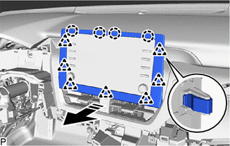
|
|
Remove in this Direction |
26. REMOVE CENTER INSTRUMENT CLUSTER FINISH PANEL SUB-ASSEMBLY (for 9 Inch Display)
(a) Disengage the 3 clips to remove the center instrument cluster finish panel sub-assembly as shown in the illustration.
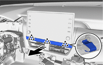
|
|
Remove in this Direction |
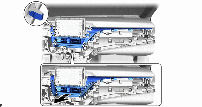
27. REMOVE CENTER INSTRUMENT CLUSTER FINISH PANEL ASSEMBLY
(a) Disengage the 4 clips in the order shown in the illustration.
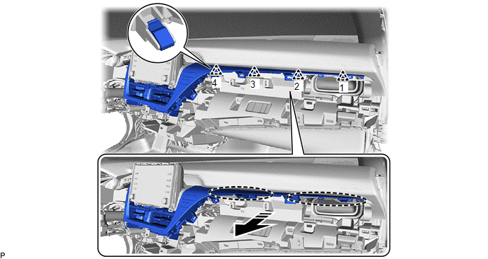
|
|
Place Hand Here |
|
Remove in this Direction |
(b) Disengage the 4 clips and 2 claws as shown in the illustration.
|
|
Place Hand Here |
|
Remove in this Direction |
(c) Disconnect each connector to remove the center instrument cluster finish panel assembly.
28. REMOVE RADIO AND DISPLAY RECEIVER ASSEMBLY WITH BRACKET (for 7 Inch Display)
Click here
29. REMOVE RADIO AND DISPLAY RECEIVER ASSEMBLY WITH BRACKET (for 9 Inch Display)
Click here
30. REMOVE FRONT DOOR SCUFF PLATE RH
HINT:
Use the same procedure as for the LH side.
31. REMOVE COWL SIDE TRIM SUB-ASSEMBLY RH
HINT:
Use the same procedure as for the LH side.
32. DISCONNECT FRONT DOOR OPENING TRIM WEATHERSTRIP RH
HINT:
Use the same procedure as for the LH side.
33. REMOVE FRONT PILLAR GARNISH RH
HINT:
Use the same procedure as for the LH side.
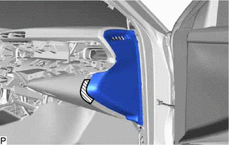
34. REMOVE INSTRUMENT SIDE PANEL RH
(a) Apply protective tape to the area shown in the illustration.
|
|
Protective Tape |
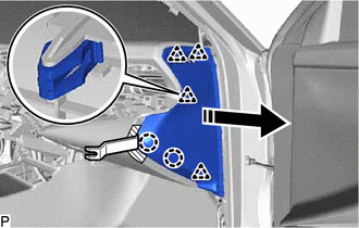
(b) Using a moulding remover, disengage the 2 claws and 4 clips as shown in the illustration.
|
|
Remove in this Direction |
NOTICE:
To prevent damage to the instrument side panel RH, do not insert the moulding remover in a position other than shown in the illustration.
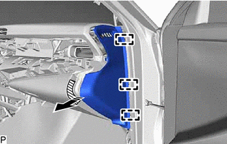
(c) Disengage the 3 guides to remove the instrument side panel RH as shown in the illustration.
|
|
Remove in this Direction |
35. REMOVE NO. 2 INSTRUMENT PANEL UNDER COVER SUB-ASSEMBLY
(a) Disengage the 4 claws as shown in the illustration.
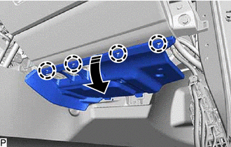
|
|
Remove in this Direction |
(b) Disengage the 2 guides as shown in the illustration.
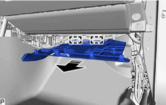
|
|
Remove in this Direction |
(c) Disengage the clamp.
(d) Disconnect the connector to remove the No. 2 instrument panel under cover sub-assembly.
36. REMOVE LOWER NO. 2 INSTRUMENT PANEL AIRBAG ASSEMBLY
Click here
37. REMOVE LOWER INSTRUMENT PANEL SUB-ASSEMBLY
| (a) Remove the 5 screws <C>. |
|
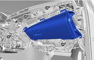
(b) Disengage the 4 claws as shown in the illustration.
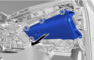
|
|
Remove in this Direction |
(c) Disconnect the connector to remove the lower instrument panel sub-assembly.
38. REMOVE NO. 1 INSTRUMENT PANEL SPEAKER PANEL
(a) Disengage the 2 clips as shown in the illustration.
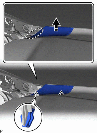
|
|
Place Hand Here |
|
|
Remove in this Direction |
(b) Disengage the 2 guides to remove the No. 1 instrument panel speaker panel as shown in the illustration.
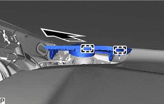
|
|
Remove in this Direction |
39. REMOVE FRONT NO. 2 SPEAKER ASSEMBLY (for LH Side)
Click here
40. REMOVE NO. 2 INSTRUMENT PANEL SPEAKER PANEL
(a) Disengage the 2 clips as shown in the illustration.
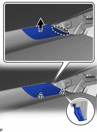
|
|
Place Hand Here |
|
|
Remove in this Direction |
(b) Disengage the 2 guides to remove the No. 2 instrument panel speaker panel as shown in the illustration.
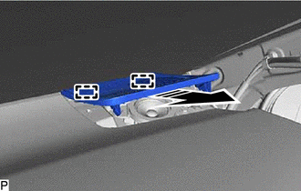
|
|
Remove in this Direction |
41. REMOVE FRONT NO. 2 SPEAKER ASSEMBLY (for RH Side)
HINT:
Use the same procedure as for the LH side.
42. REMOVE NO. 1 INSTRUMENT PANEL GARNISH SUB-ASSEMBLY
(a) Disengage the 4 clips to remove the No. 1 instrument panel garnish sub-assembly as shown in the illustration.
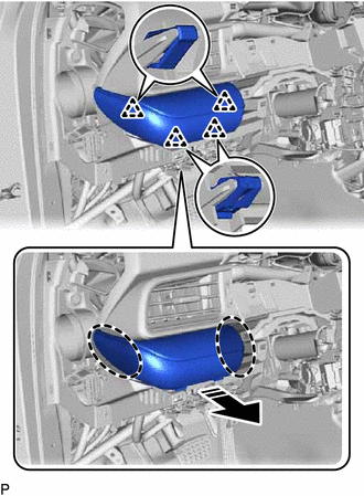
|
|
Place Hand Here |
|
|
Remove in this Direction |
43. REMOVE NO. 1 INSTRUMENT PANEL REGISTER ASSEMBLY
(a) Disengage the 2 clips and 2 claws to remove the No. 1 instrument panel register assembly as shown in the illustration.
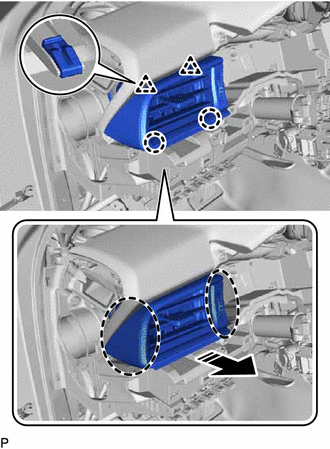
|
|
Place Hand Here |
|
|
Remove in this Direction |
44. DISCONNECT NO. 5 INSTRUMENT PANEL WIRE
Click here
45. REMOVE INSTRUMENT PANEL SAFETY PAD SUB-ASSEMBLY
(a) Disengage the 2 claws to disconnect the cooler (room temp. sensor) thermistor as shown in the illustration.
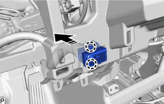
|
|
Remove in this Direction |
(b) Disconnect each connector.
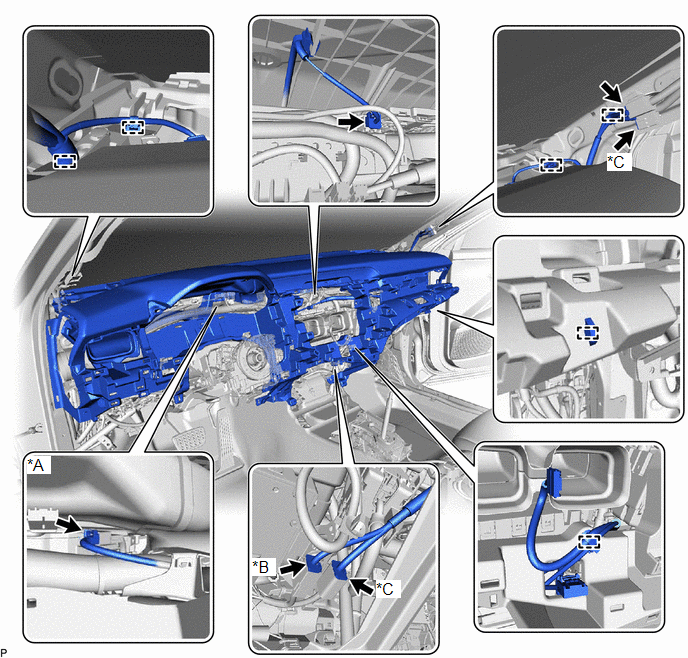
|
*A | w/ Headup Display |
*B | w/ Navigation System |
|
*C | w/ Manual (SOS) Switch |
- | - |
(c) Disengage each clamp.
(d) Remove the 2 clips.
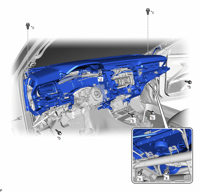
|
*a | Bolt <A> |
*b | Bolt <B> |
|
*c | Clip |
*d | Nut <E> |
(e) Remove the 4 bolts <B>, 2 bolts <A> and nut <E>.
(f) Disengage the 4 guides and remove the instrument panel safety pad sub-assembly as shown in the illustration.
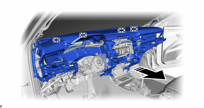
|
|
Remove in this Direction |
- | - |
NOTICE:
- Do not damage the instrument panel safety pad sub-assembly.
- Do not allow the wire harnesses to interfere with the surrounding parts.
READ NEXT:
SEE MORE:
 Summary of functions
The multi-information display presents the driver with a variety of driving-
related data, such as the current outside temperature. The multiinformation
display can also be used to change the display settings
and other settings.
Shift position
Menu icon display area
Displays the follow
Initialization Switch Error (for Test Diagnosis) (C2198)
DESCRIPTION The switch circuit inside the combination meter assembly turns on and off according to the steering pad switch assembly operation.
During test mode, the tire pressure warning light blinks at 0.125 second intervals when "Set Pressure" is selected on the multi-information display, and il
