Toyota Camry (XV70): Low or High Power Supply Voltage (C1241)
DESCRIPTION
If a malfunction in the power source circuit occurs, or a malfunction in communication with the skid control ECU (brake actuator assembly) or in a speed sensor occurs, the 4WD ECU assembly will prohibit operations by the fail-safe function.
|
DTC No. | Detection Item |
DTC Detection Condition | Trouble Area |
|---|---|---|---|
|
C1241 | Low or High Power Supply Voltage |
|
|
|
Vehicle Condition | |||||
|---|---|---|---|---|---|
|
Pattern 1 | Pattern 2 |
Pattern 3 | Pattern 4 | ||
|
Diagnosis Condition | At a vehicle speed of 3 km/h (2 mph) or more |
○ | - |
- | - |
|
With the IG1 terminal voltage 9.5 V or less |
- | ○ |
- | - | |
|
With the IG1 terminal voltage 17 V or more |
- | - |
- | ○ | |
|
Malfunction Status | Voltage of IG1 terminal is 9.5 V or less. |
○ | - |
- | - |
|
Communication with the skid control ECU (brake actuator assembly) is impossible. |
- | ○ |
- | ○ | |
|
Vehicle speed sensor voltage is reduced. |
- | - |
○ | - | |
|
Detection Time | 10 seconds or more |
- | 60 seconds or more |
3 seconds or more | |
|
Number of Trips | 1 trip |
1 trip | 1 trip |
1 trip | |
HINT:
DTC will be output when conditions for any of the patterns in the table above are met.
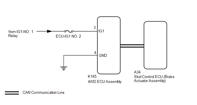
WIRING DIAGRAM
CAUTION / NOTICE / HINT
NOTICE:
Inspect the fuses for circuits related to this system before performing the following inspection procedure.
PROCEDURE
| 1. |
CHECK FOR DTC (CAN COMMUNICATION SYSTEM AND VEHICLE STABILITY CONTROL SYSTEM) |
(a) Check if CAN communication system DTCs are output.
Click here
.gif)
(b) Start the engine.
(c) Drive the vehicle, accelerate to a speed of 3 km/h (2 mph) or more for 60 seconds or more, and check if the speed sensor DTC (vehicle stability control system DTC) is output.
Chassis > Brake > Trouble Codes|
Result | Proceed to |
|---|---|
|
Neither CAN communication system DTC nor speed sensor DTC (vehicle stability control system DTC) is output |
A |
| CAN communication system DTC is output |
B |
| Speed sensor DTC (vehicle stability control system DTC) is output |
C |
| B |
.gif) | GO TO CAN COMMUNICATION SYSTEM (HOW TO PROCEED WITH TROUBLESHOOTING) |
| C |
| REPAIR CIRCUIT INDICATED BY OUTPUT CODE (VEHICLE STABILITY CONTROL SYSTEM)
|
|
.gif)
| 2. |
INSPECT BATTERY |
(a) Check the battery voltage.
Standard Voltage:
11 to 14 V
| NG | | CHECK CHARGING SYSTEM |
|
| 3. |
CHECK HARNESS AND CONNECTOR (IG1 TERMINAL) |
| (a) Disconnect the K145 4WD ECU assembly connector. |
|
.png)
(b) Turn the ignition switch to ON.
(c) Measure the voltage according to the value(s) in the table below.
Standard Voltage:
|
Tester Connection | Condition |
Specified Condition |
|---|---|---|
|
K145-3 (IG1) - Body ground |
Ignition switch ON | 11 to 14 V |
| NG | | REPAIR OR REPLACE HARNESS OR CONNECTOR |
|
| 4. |
CHECK HARNESS AND CONNECTOR (GND TERMINAL) |
(a) Turn the ignition switch off.
(b) Measure the resistance according to the value(s) in the table below.
Standard Resistance:
|
Tester Connection | Condition |
Specified Condition |
|---|---|---|
|
K145-4 (GND) - Body ground |
Always | Below 1 Ω |
| NG | | REPAIR OR REPLACE HARNESS OR CONNECTOR |
|
| 5. |
RECONFIRM DTC |
(a) Clear the DTC.
Chassis > Four Wheel Drive > Clear DTCs(b) Start the engine.
(c) Drive the vehicle, accelerate to a speed of 3 km/h (2 mph) or more, and check if the same DTC is output.
Chassis > Four Wheel Drive > Trouble Codes|
Result | Proceed to |
|---|---|
|
DTC is output | A |
|
DTC is not output | B |
HINT:
Reinstall the sensor, connectors, etc. and restore the vehicle to its prior condition before rechecking DTCs.
| A |
| REPLACE 4WD ECU ASSEMBLY |
| B |
| CHECK FOR INTERMITTENT PROBLEMS
|
READ NEXT:
 Engine Circuit Malfunction (C1280)
DESCRIPTION If a malfunction in the ECM circuit occurs, the 4WD ECU assembly will output this DTC.
DTC No. Detection Item
DTC Detection Condition Trouble Area
C1280 Engine Cir
ABS Malfunction (C1296)
DESCRIPTION If a malfunction in the speed sensor signal circuit or yaw rate and acceleration sensor (airbag sensor assembly) circuit occurs, the 4WD ECU assembly will output this DTC.
The airbag sen
Steering Angle Sensor (C1297)
DESCRIPTION The 4WD ECU assembly determines that the vehicle is turning based on the signals sent from the steering sensor.
The steering sensor signal is sent to the 4WD ECU assembly via CAN communi
SEE MORE:
Internal Control Module Monitoring Processor Performance Watchdog/Safety MCU Failure (P060A47)
MONITOR DESCRIPTION The main CPU and sub CPU of the ECM perform data communication between each other. The main CPU monitors the communications and WDC pulses from the sub CPU. When the signal malfunctions below are detected, this DTC is stored.
DTC No. Detection Item
DTC Detection Cond
Mute Signal Circuit between Stereo Component Amplifier and Telematics Transceiver
DESCRIPTION The DCM (telematics transceiver) sends a mute signal to the stereo component amplifier assembly.
The stereo component amplifier assembly controls the volume according to the mute signal from the DCM (telematics transceiver). WIRING DIAGRAM
CAUTION / NOTICE / HINT
NOTICE:
Depen
