Toyota Camry (XV70): Mute Signal Circuit between Stereo Component Amplifier and Telematics Transceiver
DESCRIPTION
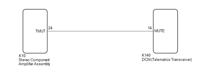
The DCM (telematics transceiver) sends a mute signal to the stereo component amplifier assembly.
The stereo component amplifier assembly controls the volume according to the mute signal from the DCM (telematics transceiver).
WIRING DIAGRAM
CAUTION / NOTICE / HINT
NOTICE:
- Depending on the parts that are replaced during vehicle inspection or maintenance, performing initialization, registration or calibration may be needed. Refer to Precaution for Audio and Visual System.
Click here
.gif)
- When replacing the radio and display receiver assembly, always replace it with a new one. If a radio and display receiver assembly which was installed to another vehicle is used, the following may occur:
- A communication malfunction DTC may be stored.
- The radio and display receiver assembly may not operate normally.
- Before replacing the DCM (telematics transceiver), refer to Registration.
Click here
PROCEDURE
|
1. | INSPECT DCM (TELEMATICS TRANSCEIVER) |
| (a) Measure the voltage according to the value(s) in the table below. Standard Voltage:
|
|
| OK | .gif) | PROCEED TO NEXT SUSPECTED AREA SHOWN IN PROBLEM SYMPTOMS TABLE
|
|
.gif)
| 2. |
CHECK HARNESS AND CONNECTOR (STEREO COMPONENT AMPLIFIER ASSEMBLY - DCM (TELEMATICS TRANSCEIVER)) |
(a) Disconnect the K10 stereo component amplifier assembly connector.
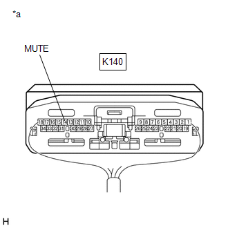
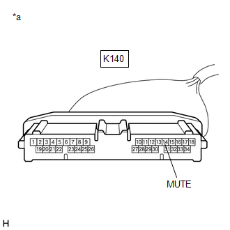
(b) Disconnect the K140 DCM (telematics transceiver) connector.
(c) Measure the resistance according to the value(s) in the table below.
Standard Resistance:
|
Tester Connection | Condition |
Specified Condition |
|---|---|---|
|
K10-24 (TMUT) - K140-14 (MUTE) |
Always | Below 1 Ω |
|
K10-24 (TMUT) or K140-14 (MUTE) - Body ground |
Always | 10 kΩ or higher |
| NG | | REPAIR OR REPLACE HARNESS OR CONNECTOR |
|
| 3. |
INSPECT STEREO COMPONENT AMPLIFIER ASSEMBLY |
(a) Disconnect the K140 DCM (telematics transceiver) connector.
| (b) Measure the voltage according to the value(s) in the table below. Standard Voltage:
|
|
| OK | | REPLACE DCM (TELEMATICS TRANSCEIVER)
|
| NG | | REPLACE STEREO COMPONENT AMPLIFIER ASSEMBLY
|
READ NEXT:
 Mute Signal Circuit between Radio Receiver and Telematics Transceiver
DESCRIPTION The DCM (telematics transceiver) sends a mute signal to the radio and display receiver assembly.
The radio and display receiver assembly controls the volume according to the mute signal
AVC-LAN Circuit
DESCRIPTION Each unit of the audio and visual system connected to the AVC-LAN (communication bus) transmits signals via AVC-LAN communication.
If a short to +B or short to ground occurs in an AVC-LA
Vehicle Speed Signal Circuit between Stereo Component Amplifier and Combination Meter
DESCRIPTION The stereo component amplifier assembly receives a vehicle speed signal from the combination meter assembly to control the ASL function.
HINT:
A voltage of 12 V or 5 V is output from
SEE MORE:
AWD Warning Remains ON
DESCRIPTION The 4WD ECU assembly is connected to the combination meter assembly via CAN communication.
If the 4WD ECU assembly stores any DTCs which are related to the dynamic torque control AWD system, the warning message is displayed on the multi-information display in the combination meter asse
Throttle/Pedal Position Sensor/Switch "B" Circuit Short to Ground (P022011)
DESCRIPTION Refer to DTC P012011. Click here
DTC No. Detection Item
DTC Detection Condition Trouble Area
MIL Memory
Note P022011
Throttle/Pedal Position Sensor/Switch "B" Circuit Short to Ground
The output voltage of VTA2 is less than 2.05 V for 2 secon
