Toyota Camry (XV70): On-vehicle Inspection
ON-VEHICLE INSPECTION
PROCEDURE
1. INSPECT AUTOMATIC LIGHT CONTROL SENSOR
|
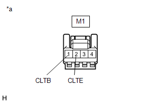
*a | Front view of wire harness connector (to Automatic Light Control Sensor) |
(a) Disconnect the M1 automatic light control sensor connector.
(b) Measure the voltage and resistance according to the value(s) in the table below.
Standard Voltage:
|
Tester Connection | Condition |
Specified Condition |
|---|---|---|
|
M1-1 (CLTB) - M1-2 (CLTE) |
Ignition switch off |
Below 1 V |
|
Ignition switch ON |
11 to 14 V |
Standard Resistance:
|
Tester Connection | Condition |
Specified Condition |
|---|---|---|
|
M1-2 (CLTE) - Body ground |
Always | Below 1 Ω |
If the result is not as specified, there may be a malfunction on the wire harness side.
(c) Connect the M1 automatic light control sensor connector.
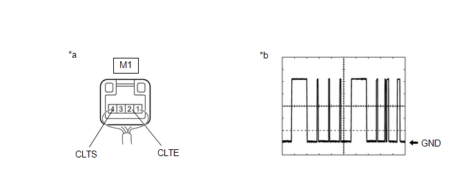
(d) Connect an oscilloscope to terminals M1-2 (CLTE) and M1-4 (CLTS) of the automatic light control sensor connector and check the waveform.
|
*a | Component with harness connected (Automatic Light Control Sensor) |
*b | Waveform |
OK:
|
Tester Connection | Condition |
Tool Setting | Specified Condition |
|---|---|---|---|
|
M1-2 (CLTE) - M1-4 (CLTS) |
Ignition switch ON |
2 V/DIV., 10 ms./DIV. |
Pulse generation (See waveform) |
HINT:
The communication waveform changes according to the surrounding brightness.
If the result is not as specified, the automatic light control sensor may be malfunctioning.
READ NEXT:
 Removal
REMOVAL CAUTION / NOTICE / HINT
The necessary procedures (adjustment, calibration, initialization, or registration) that must be performed after parts are removed and installed, or replaced during
Installation
INSTALLATION PROCEDURE 1. INSTALL AUTOMATIC LIGHT CONTROL SENSOR
(a) Engage the 2 claws to install the automatic light control sensor.
(b) Connect the connector. 2. INSTALL DEFROSTER NOZZLE ASSE
Back-up Light Bulb
ReplacementREPLACEMENT CAUTION / NOTICE / HINT
HINT:
Use the same procedure for the RH side and LH side.
The following procedure is for the LH side.
PROCEDURE 1. REMOVE LUGGAGE COMP
SEE MORE:
On-vehicle Inspection
ON-VEHICLE INSPECTION PROCEDURE
1. INSPECT COOLING FAN SYSTEM CAUTION: To prevent injury due to contact with an operating cooling fan, keep your hands and clothing away from the cooling fan when inspecting the cooling fan system.
(a) Connect the Techstream to the DLC3.
(b) Turn the engine swi
General Information
GENERAL INFORMATION GENERAL DESCRIPTION (a) This manual is written in accordance with SAE J2008.
(b) Repair operations can be separated mainly into the following 3 processes:
(1) Diagnosis (2) Removing/Installing, Replacing, Disassembling/Reassembling, Checking and Adjusting
(3) Final Inspecti
