Toyota Camry (XV70): On-vehicle Inspection
ON-VEHICLE INSPECTION
PROCEDURE
1. INSPECT STOP LIGHT SWITCH ASSEMBLY
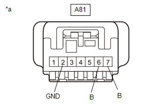
(a) Disconnect the A81 stop light switch assembly connector.
| (b) Measure the voltage and resistance on the wire harness side connector according to the value(s) in the table below. Standard Voltage:
Standard Resistance:
If the result is not as specified, repair or replace the wire harness or connector. |
|
| (c) Connect the A81 stop light switch assembly connector. |
|
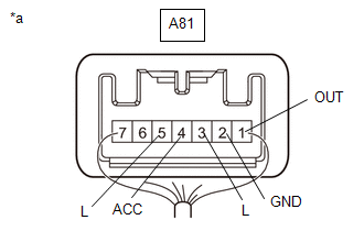
(d) Measure the voltage according to the value(s) in the table below.
Standard Voltage:
|
Tester Connection | Condition |
Specified Condition |
|---|---|---|
|
A81-1 (OUT) - A81-2 (GND) |
Ignition switch off, brake pedal not depressed |
Below 1 V |
|
A81-1 (OUT) - A81-2 (GND) |
Ignition switch off, brake pedal depressed |
11 to 14 V |
|
A81-3 (L) - A81-2 (GND) |
Ignition switch off, brake pedal not depressed |
Below 1 V |
|
A81-3 (L) - A81-2 (GND) |
Ignition switch off, brake pedal depressed |
11 to 14 V |
|
A81-4 (ACC) - A81-2 (GND) |
Always | 11 to 14 V |
|
A81-5 (L) - A81-2 (GND) |
Ignition switch ON, brake pedal not depressed |
11 to 14 V |
|
A81-5 (L) - A81-2 (GND) |
Ignition switch ON, brake pedal depressed |
Below 1 V |
If the result is not as specified, replace the stop light switch assembly.
READ NEXT:
 Removal
REMOVAL PROCEDURE 1. REMOVE NO. 1 INSTRUMENT PANEL UNDER COVER SUB-ASSEMBLY
Click here
2. REMOVE STOP LIGHT SWITCH ASSEMBLY
(a) Disconnect the connector.
(b) Tu
Installation
INSTALLATION PROCEDURE 1. INSTALL STOP LIGHT SWITCH ASSEMBLY
(a) Insert the stop light switch assembly until the threaded sleeve hits the pedal.
NOTICE: When inserting the stop light switch
SEE MORE:
Jam Protection Function does not Operate
DESCRIPTION This symptom may occur for any of the power windows.
The jam protection function operates within a specified range during the manual up or auto up operation. CAUTION / NOTICE / HINT
NOTICE:
If a power window regulator motor assembly has been replaced with a new one, initializ
Reassembly
REASSEMBLY CAUTION / NOTICE / HINT
HINT:
Use the same procedure for the RH side and LH side.
The following procedure is for the LH side.
PROCEDURE 1. INSTALL FRONT AXLE OUTBOARD JOINT BOOT
(a) Secure the drive shaft in a vise between aluminum plates. NOTICE:
Do not overtighten the
