Toyota Camry (XV70): Outer Mirror Switch
Components
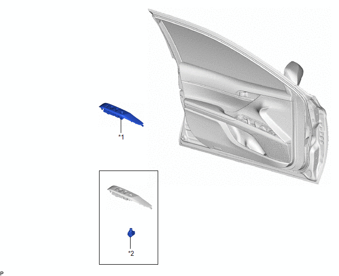
COMPONENTS
ILLUSTRATION
|
*1 | MULTIPLEX NETWORK MASTER SWITCH ASSEMBLY WITH FRONT DOOR UPPER ARMREST BASE PANEL |
*2 | OUTER MIRROR SWITCH ASSEMBLY |
Removal
REMOVAL
PROCEDURE
1. REMOVE MULTIPLEX NETWORK MASTER SWITCH ASSEMBLY WITH FRONT DOOR UPPER ARMREST BASE PANEL
Click here .gif)
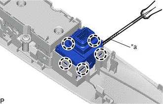
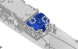
2. REMOVE OUTER MIRROR SWITCH ASSEMBLY
| (a) Using a screwdriver, disengage the 5 claws and remove the outer mirror switch assembly. HINT: Tape the screwdriver tip before use. |
|
Inspection
INSPECTION
PROCEDURE
1. INSPECT OUTER MIRROR SWITCH ASSEMBLY
(a) Check the mirror select switch and mirror surface adjust switch.
(1) Turn the mirror select switch to the L position.
| (2) Measure the resistance according to the value(s) in the table below. Standard Resistance (for Left Side):
|
|
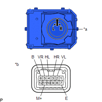
(3) Turn the mirror select switch to the R position.
(4) Measure the resistance according to the value(s) in the table below.
Standard Resistance (for Right Side):
|
Tester Connection | Condition |
Specified Condition |
|---|---|---|
|
5 (VR) - 6 (B) 11 (M+) - 7 (E) |
Up | Below 1 Ω |
|
Off | 10 kΩ or higher | |
|
5 (VR) - 7 (E) 11 (M+) - 6 (B) |
Down | Below 1 Ω |
|
Off | 10 kΩ or higher | |
|
3 (HR) - 6 (B) 11 (M+) - 7 (E) |
Left | Below 1 Ω |
|
Off | 10 kΩ or higher | |
|
3 (HR) - 7 (E) 11 (M+) - 6 (B) |
Right | Below 1 Ω |
|
Off | 10 kΩ or higher |
If the result is not as specified, replace the outer mirror switch assembly.
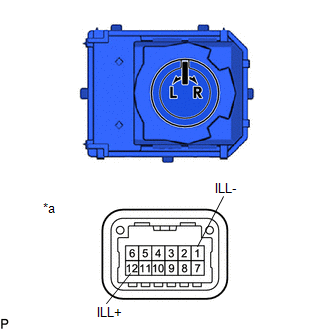
(b) Check that the LED illuminates.
| (1) Apply auxiliary battery voltage to the outer mirror switch assembly and check that the LED illuminates. OK:
If the result is not as specified, replace the outer mirror switch assembly. |
|
Installation
INSTALLATION
PROCEDURE
1. INSTALL OUTER MIRROR SWITCH ASSEMBLY
| (a) Engage the 5 claws to install the outer mirror switch assembly. |
|
2. INSTALL MULTIPLEX NETWORK MASTER SWITCH ASSEMBLY WITH FRONT DOOR UPPER ARMREST BASE PANEL
Click here .gif)
READ NEXT:
 Components
COMPONENTS ILLUSTRATION
*A for Front Passenger Side
*B for Driver Side
*C w/o Courtesy Light
*D w/ Courtesy Light
*1 COURTESY LIGHT ASSEMBLY
Removal
REMOVAL CAUTION / NOTICE / HINT
The necessary procedures (adjustment, calibration, initialization, or registration) that must be performed after parts are removed and installed, or replaced during
SEE MORE:
Parts Location
PARTS LOCATION ILLUSTRATION
*1 INTAKE AIR CONTROL VALVE (for ACIS)
*2 ECM
*3 ENGINE ROOM RELAY BLOCK AND JUNCTION BLOCK ASSEMBLY
- EFI NO. 1 FUSE -
-
Installation
INSTALLATION PROCEDURE 1. INSTALL ENGINE COVER BRACKET
(a) Install the engine cover bracket to the cylinder head cover sub-assembly LH with the bolt.
Torque: 10 N·m {102 kgf·cm, 7 ft·lbf} 2. INSTALL WATER FILLER BRACKET
(a) Temporarily install the water filler bracket to the camshaft h
