
Toyota Camry (XV70): Components
COMPONENTS
ILLUSTRATION
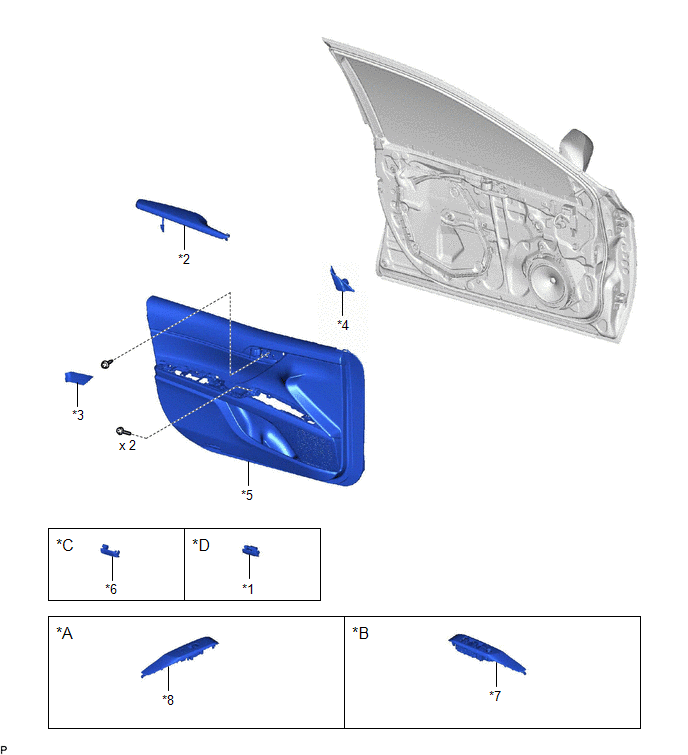
|
*A | for Front Passenger Side |
*B | for Driver Side |
|
*C | w/o Courtesy Light |
*D | w/ Courtesy Light |
|
*1 | COURTESY LIGHT ASSEMBLY |
*2 | FRONT ARMREST ASSEMBLY |
|
*3 | FRONT DOOR ARMREST COVER SUB-ASSEMBLY |
*4 | FRONT DOOR LOWER FRAME BRACKET GARNISH |
|
*5 | FRONT DOOR TRIM BOARD SUB-ASSEMBLY |
*6 | FRONT DOOR TRIM PLATE |
|
*7 | MULTIPLEX NETWORK MASTER SWITCH ASSEMBLY WITH FRONT DOOR UPPER ARMREST BASE PANEL |
*8 | POWER WINDOW REGULATOR SWITCH ASSEMBLY WITH FRONT DOOR UPPER ARMREST BASE PANEL |
ILLUSTRATION
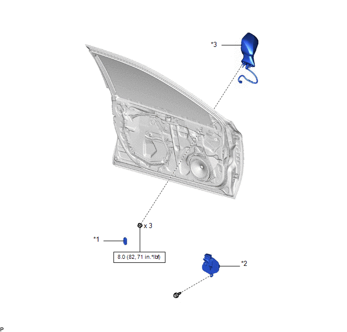
|
*1 | HOLE PLUG |
*2 | OUTER MIRROR INSTALL HOLE COVER |
|
*3 | OUTER REAR VIEW MIRROR ASSEMBLY WITH COVER |
- | - |
.png) |
N*m (kgf*cm, ft.*lbf): Specified torque |
- | - |
ILLUSTRATION
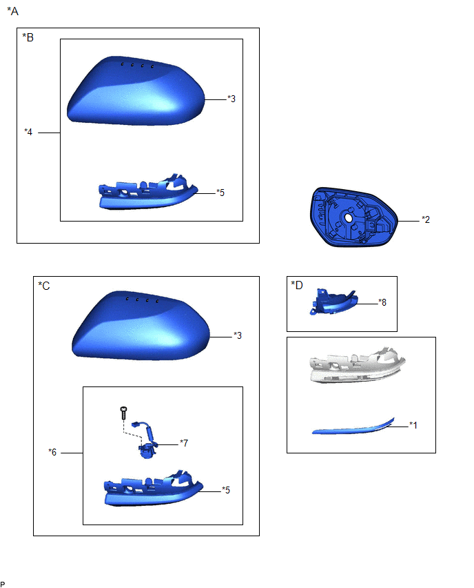
|
*A | for Type A |
*B | w/o Panoramic View Monitor System |
|
*C | w/ Panoramic View Monitor System |
*D | w/ Side Turn Signal Light |
|
*1 | NO. 2 OUTER MIRROR COVER |
*2 | OUTER MIRROR |
|
*3 | OUTER MIRROR COVER |
*4 | OUTER MIRROR COVER WITH OUTER MIRROR HOLE COVER |
|
*5 | OUTER MIRROR HOLE COVER ASSEMBLY |
*6 | OUTER MIRROR HOLE COVER WITH SIDE TELEVISION CAMERA ASSEMBLY |
|
*7 | SIDE TELEVISION CAMERA ASSEMBLY |
*8 | SIDE TURN SIGNAL LIGHT ASSEMBLY |
ILLUSTRATION
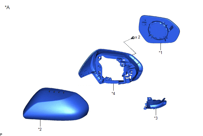
|
*A | for Type B |
- | - |
|
*1 | OUTER MIRROR |
*2 | OUTER MIRROR COVER |
|
*3 | SIDE TURN SIGNAL LIGHT ASSEMBLY |
*4 | VISOR HOUSING |
READ NEXT:
 Removal
REMOVAL CAUTION / NOTICE / HINT
The necessary procedures (adjustment, calibration, initialization, or registration) that must be performed after parts are removed and installed, or replaced during
Disassembly
DISASSEMBLY CAUTION / NOTICE / HINT
HINT:
Use the same procedure for the RH side and LH side.
The following procedure is for the LH side.
PROCEDURE 1. REMOVE OUTER MIRROR (for Type
Inspection
INSPECTION PROCEDURE 1. INSPECT OUTER REAR VIEW MIRROR ASSEMBLY RH (w/o Panoramic View Monitor System)
(a) Check the operation of the mirror surface. NOTICE: If the mirror surface is fully turned t
SEE MORE:
Mass or Volume Air Flow Sensor "A" Circuit Short to Battery (P010012,P010014)
DESCRIPTION The mass air flow meter sub-assembly is a sensor that measures the intake air volume using the following built-in components:
By-pass duct (allows some of the intake air to flow past a silicon chip sensor)
Silicon chip sensor (uses a heater control bridge circuit and temperatur
EVAP System
RELATED DTCS
DTC No. SAE
Monitoring Item Link
P00FE00 P00FE
EVAP vent line blocked
P043E00 P043E
Reference orifice clogged (built into canister pump module)
P043F00 P043F
Reference orifice high-flow (built into canister
