
Toyota Camry (XV70): Disassembly
DISASSEMBLY
CAUTION / NOTICE / HINT
HINT:
- Use the same procedure for the RH side and LH side.
- The following procedure is for the LH side.
PROCEDURE
1. REMOVE OUTER MIRROR (for Type A)
Click here .gif)
2. REMOVE OUTER MIRROR COVER WITH OUTER MIRROR HOLE COVER (for Type A)
w/o Panoramic View Monitor System:
Click here
3. REMOVE OUTER MIRROR COVER (for Type A)
Click here
4. REMOVE OUTER MIRROR HOLE COVER WITH SIDE TELEVISION CAMERA ASSEMBLY (for Type A)
w/ Panoramic View Monitor System:
Click here
5. REMOVE SIDE TELEVISION CAMERA ASSEMBLY (for Type A)
w/ Panoramic View Monitor System:
Click here
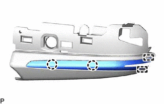
6. REMOVE NO. 2 OUTER MIRROR COVER (for Type A)
| (a) Disengage the 2 claws and 2 guides to remove the No. 2 outer mirror cover. |
|
7. REMOVE OUTER MIRROR (for Type B)
Click here
8. REMOVE OUTER MIRROR COVER (for Type B)
Click here
9. REMOVE VISOR HOUSING (for Type B)
| (a) Using a T25 "TORX" socket wrench, remove the 2 screws. |
|
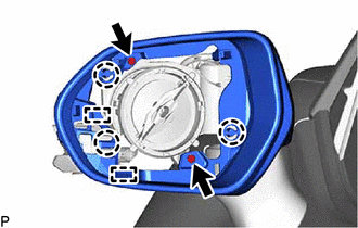
(b) Disengage the 3 claws and 2 guides to remove the visor housing.
10. REMOVE SIDE TURN SIGNAL LIGHT ASSEMBLY (w/ Side Turn Signal Light)
Click here
READ NEXT:
 Inspection
INSPECTION PROCEDURE 1. INSPECT OUTER REAR VIEW MIRROR ASSEMBLY RH (w/o Panoramic View Monitor System)
(a) Check the operation of the mirror surface. NOTICE: If the mirror surface is fully turned t
Reassembly
REASSEMBLY CAUTION / NOTICE / HINT
HINT:
Use the same procedure for the RH side and LH side.
The following procedure is for the LH side.
PROCEDURE 1. INSTALL SIDE TURN SIGNAL LIGHT
Installation
INSTALLATION CAUTION / NOTICE / HINT
HINT:
Use the same procedure for the RH side and LH side.
The following procedure is for the LH side.
PROCEDURE 1. INSTALL OUTER REAR VIEW MIRRO
SEE MORE:
Doors
Unlocking and locking the doors from the outside
◆ Smart key system (if equipped)
Carry the electronic key to enable this function.
Grip the driver's door handle
to unlock the door. Holding
the driver's door handle for
approximately 2 seconds
unlocks all the doors. Grip
the front p
Cellular Phone Registration Failure
CAUTION / NOTICE / HINT
NOTICE:
Depending on the parts that are replaced during vehicle inspection or maintenance, performing initialization, registration or calibration may be needed. Refer to Precaution for Navigation System.
Click here
When replacing the radio and display receiver
