
Toyota Camry (XV70): Disassembly
DISASSEMBLY
PROCEDURE
1. REMOVE NO. 3 AIR DUCT SUB-ASSEMBLY
| (a) Remove the 2 screws. |
|
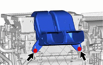
| (b) Disengage the 4 claws to remove the No. 3 air duct sub-assembly. |
|
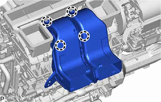
2. REMOVE NO. 2 AIR DUCT SUB-ASSEMBLY
| (a) Disengage the 4 claws to remove the No. 2 air duct sub-assembly. |
|
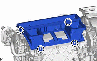
3. REMOVE NO. 2 AIR DUCT
(a) Remove the screw.
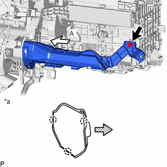
|
*a | View A |
.png) |
Front |
(b) Disengage the 3 claws to remove the No. 2 air duct.
NOTICE:
Be careful not to deform or damage the lower heater case of the air conditioner unit assembly when removing the No. 2 air duct.
4. REMOVE GROMMET (for Manual Air Conditioning System)
| (a) Disengage the 2 claws to remove the grommet. |
|
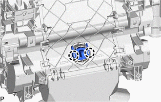
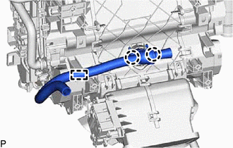
5. REMOVE ASPIRATOR (for Automatic Air Conditioning System)
| (a) Disengage the guide and 2 claws to remove the aspirator. |
|
6. REMOVE BLOWER ASSEMBLY
Click here
.gif)
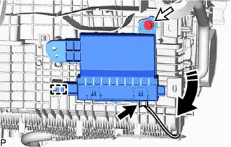
7. REMOVE AIR CONDITIONING AMPLIFIER ASSEMBLY
(a) Disconnect the connector.
.png) |
Remove in this Direction |
(b) Remove the screw.
(c) Disengage the guide to remove the air conditioning amplifier assembly as shown in the illustration.
8. REMOVE AIR CONDITIONING HARNESS ASSEMBLY
(a) for Single Type:
| (1) Disconnect each connector. |
|
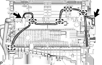
(2) Disengage each clamp to remove the air conditioning harness assembly.
(b) for Dual Type:
| (1) Disconnect each connector. |
|
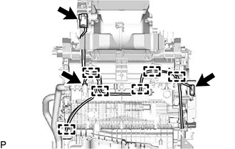
(2) Disengage each clamp to remove the air conditioning harness assembly.
9. REMOVE HEATER COVER
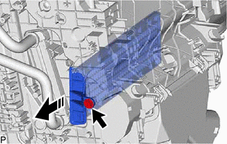
(a) Remove the screw.
|
|
Remove in this Direction |
(b) Remove the heater cover as shown in the illustration.
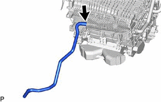
10. REMOVE DRAIN COOLER HOSE
| (a) Remove the drain cooler hose. |
|
11. REMOVE NO. 1 AIR CONDITIONING RADIATOR DAMPER SERVO SUB-ASSEMBLY
| (a) Remove the 3 screws and No. 1 air conditioning radiator damper servo sub-assembly. |
|
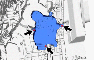
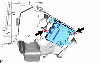
12. REMOVE NO. 2 AIR CONDITIONING RADIATOR DAMPER SERVO SUB-ASSEMBLY (for Dual Type)
| (a) Remove the 2 screws and No. 2 air conditioning radiator damper servo sub-assembly. |
|
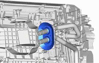
13. REMOVE HEATER PIPE GROMMET
| (a) Remove the heater pipe grommet. |
|
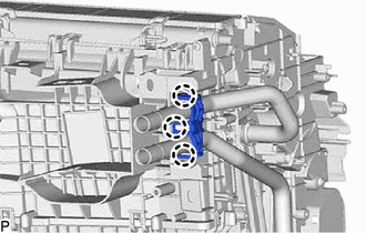
14. REMOVE HEATER CLAMP
|
(a) Disengage the 3 claws to remove the heater clamp. |
|
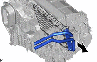
15. REMOVE HEATER RADIATOR UNIT SUB-ASSEMBLY
|
|
Remove in this Direction |
(a) Remove the heater radiator unit sub-assembly as shown in the illustration.
NOTICE:
Prepare a drain pan or cloth in case the coolant leaks.
16. REMOVE GROMMET SUB-ASSEMBLY
| (a) Remove the grommet sub-assembly. |
|
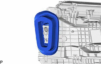
17. REMOVE COOLER EXPANSION VALVE
| (a) Using a 4 mm hexagon socket wrench, remove the 2 hexagon bolts and cooler expansion valve. |
|
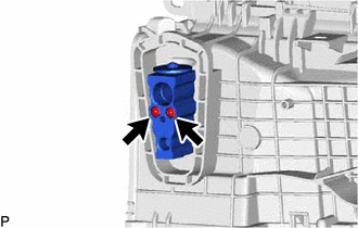
(b) Remove the 2 O-rings from the No. 1 cooler evaporator sub-assembly.
18. REMOVE NO. 1 COOLER EVAPORATOR SUB-ASSEMBLY
(a) Remove the 2 screws.
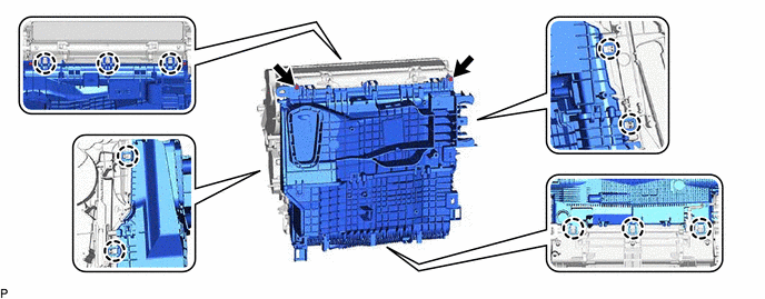
(b) Disengage the 10 claws to remove the upper heater case with No. 1 cooler evaporator sub-assembly from the lower heater case.
| (c) Disengage the clamp. |
|
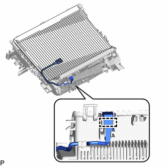
(d) Remove the No. 1 cooler evaporator sub-assembly with No. 1 cooler thermistor from the upper heater case.
NOTICE:
When the No. 1 cooler evaporator sub-assembly is removed, make sure to install a new one. The No. 1 cooler evaporator sub-assembly cannot be reused.
19. REMOVE NO. 1 COOLER THERMISTOR
Click here
READ NEXT:
 Reassembly
REASSEMBLY PROCEDURE 1. INSTALL NO. 1 COOLER THERMISTOR
Click here 2. INSTALL NO. 1 COOLER EVAPORATOR SUB-ASSEMBLY
(a) Install the No. 1 cooler evaporator sub-assembly with No. 1 cooler thermi
Installation
INSTALLATION PROCEDURE 1. TEMPORARILY INSTALL AIR CONDITIONER UNIT ASSEMBLY
(a) w/ Claw: (1) Engage the 2 claws. (b) Temporarily install the air conditioner unit assembly to the instrument panel rein
Ambient Temperature Sensor
ComponentsCOMPONENTS ILLUSTRATION
*A for Bar Type Radiator Grille
*B for Mesh Type Radiator Grille
*1 FRONT RADIATOR SIDE AIR GUIDE PLATE RH
*2 THERMISTOR ASSEMBLY R
SEE MORE:
Components
COMPONENTS ILLUSTRATION
*1 REAR ENGINE UNDER COVER LH
*2 FRONT FENDER APRON SEAL LH
*3 NO. 1 ENGINE UNDER COVER
*4 FRONT WHEEL OPENING EXTENSION PAD LH
*5 FRONT WHEEL OPENING EXTENSION PAD RH
- -
N*m (kgf*cm, ft.*lbf): Specified
Operation not Accepted Even If Air Conditioning Switch is Operated
DESCRIPTION If the air conditioning system cannot be operated using the air conditioning control assembly, the following suspected areas may be the cause.
Symptom Factor
Air conditioning system cannot be operated using air conditioning control assembly
(With the exception of the
