Toyota Camry (XV70): Removal
REMOVAL
CAUTION / NOTICE / HINT
The necessary procedures (adjustment, calibration, initialization, or registration) that must be performed after parts are removed and installed, or replaced during outer rear view mirror assembly with cover removal/installation are shown below.
Necessary Procedure After Parts Removed/Installed/Replaced|
Replaced Part or Performed Procedure |
Necessary Procedure | Effect/Inoperative Function when Necessary Procedure not Performed |
Link |
|---|---|---|---|
| *1: Applies only for when removing and installing or replacing the rear television camera assembly. | |||
| Side television camera view adjustment |
Panoramic View Monitor System |
|
Replacement or removal and installation of 2 or more parts:
|
| ||
HINT:
- Use the same procedure for the RH side and LH side.
- The following procedure is for the LH side.
PROCEDURE
1. REMOVE FRONT DOOR LOWER FRAME BRACKET GARNISH
Click here .gif)
2. REMOVE FRONT DOOR ARMREST COVER SUB-ASSEMBLY
Click here
3. REMOVE MULTIPLEX NETWORK MASTER SWITCH ASSEMBLY WITH FRONT DOOR UPPER ARMREST BASE PANEL (for Driver Side)
Click here
4. REMOVE POWER WINDOW REGULATOR SWITCH ASSEMBLY WITH FRONT DOOR UPPER ARMREST BASE PANEL (for Front Passenger Side)
Click here
5. REMOVE FRONT ARMREST ASSEMBLY
Click here
6. REMOVE FRONT DOOR TRIM PLATE (w/o Courtesy Light)
Click here
7. REMOVE COURTESY LIGHT ASSEMBLY (w/ Courtesy Light)
Click here
8. REMOVE FRONT DOOR TRIM BOARD SUB-ASSEMBLY
Click here
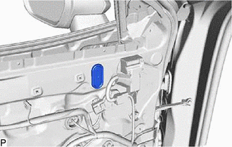
9. REMOVE HOLE PLUG
| (a) Remove the hole plug. |
|
10. REMOVE OUTER MIRROR INSTALL HOLE COVER
| (a) Disconnect the connector. |
|
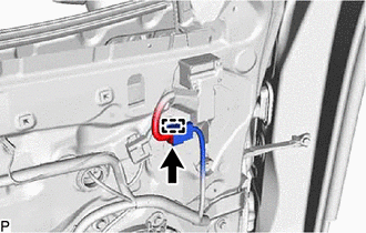
(b) Disengage the clamp.
| (c) Remove the screw. |
|
(d) Disengage the clip and 2 claws to remove the outer mirror install hole cover.
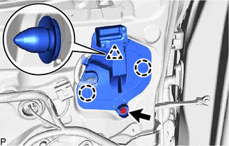
11. REMOVE OUTER REAR VIEW MIRROR ASSEMBLY WITH COVER
| (a) Disengage the clamp. |
|

(b) Remove the 3 nuts.
(c) Disengage the claw and 2 guides and remove the outer rear view mirror assembly with cover.
READ NEXT:
 Disassembly
DISASSEMBLY CAUTION / NOTICE / HINT
HINT:
Use the same procedure for the RH side and LH side.
The following procedure is for the LH side.
PROCEDURE 1. REMOVE OUTER MIRROR (for Type
Inspection
INSPECTION PROCEDURE 1. INSPECT OUTER REAR VIEW MIRROR ASSEMBLY RH (w/o Panoramic View Monitor System)
(a) Check the operation of the mirror surface. NOTICE: If the mirror surface is fully turned t
Reassembly
REASSEMBLY CAUTION / NOTICE / HINT
HINT:
Use the same procedure for the RH side and LH side.
The following procedure is for the LH side.
PROCEDURE 1. INSTALL SIDE TURN SIGNAL LIGHT
SEE MORE:
Yaw Rate Sensor Circuit Intermittent (C00631F,C006396,C05201F)
DESCRIPTION The airbag sensor assembly has a built-in yaw rate and acceleration sensor and detects the vehicle condition.
These DTCs are stored when the skid control ECU (brake actuator assembly) receives a malfunction signal from the yaw rate and acceleration sensor (airbag sensor assembly).
Inspection
INSPECTION PROCEDURE 1. INSPECT DIFFERENTIAL CASE ASSEMBLY
(a) Using SST, rotate the front differential side gear as shown in the illustration.
SST: 09528-52010 09528-05030 Standard: The front differential side gear does not lock when rotated in either direction.
If the result is not as
