Toyota Camry (XV70): Light Sensor Circuit (B1244)
DESCRIPTION
The automatic light control sensor detects ambient light. The sensor creates an electrical signal based on the amount of light detected, and sends the signal to the main body ECU (multiplex network body ECU). The main body ECU (multiplex network body ECU) turns on or off the headlights and taillights according to the signal.
|
DTC No. | Detection Item |
DTC Detection Condition |
Trouble Area | DTC Output from |
|---|---|---|---|---|
|
B1244 | Light Sensor Circuit | Detection condition:
|
| Main Body |
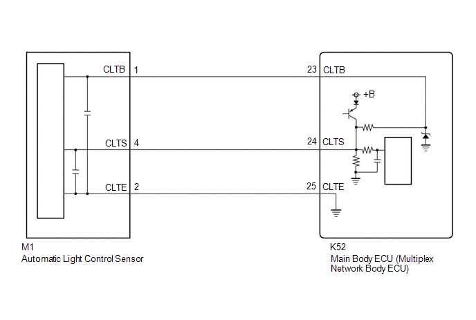
WIRING DIAGRAM
CAUTION / NOTICE / HINT
NOTICE:
Before replacing the main body ECU (multiplex network body ECU), refer to Registration.*
Click here .gif)
- *: w/ Smart Key System
PROCEDURE
|
1. | CLEAR DTC |
(a) Connect the Techstream to the DLC3.
(b) Turn the ignition switch to ON.
(c) Turn the Techstream on.
(d) Enter the following menus: Body Electrical / Main Body / Trouble Codes.
(e) Clear the DTCs.
Body Electrical > Main Body > Clear DTCs
|
.gif)
|
2. | CHECK FOR DTC |
(a) Connect the Techstream to the DLC3.
(b) Turn the ignition switch to ON.
(c) Wait 10 seconds or more.
(d) Turn the Techstream on.
(e) Enter the following menus: Body Electrical / Main Body / Trouble Codes.
(f) Check for DTCs.
Body Electrical > Main Body > Trouble CodesOK:
DTC B1244 is not output.
| OK | .gif) |
USE SIMULATION METHOD TO CHECK |
|
|
3. | READ VALUE USING TECHSTREAM |
(a) Connect the Techstream to the DLC3.
(b) Turn the ignition switch to ON.
(c) Turn the Techstream on.
(d) Enter the following menus: Body Electrical / Main Body / Data List.
(e) According to the display on the Techstream, read the Data List and check that the value of Light Sensor Illuminance changes while performing the following:
(1) Cover the automatic light control sensor with an opaque object.
(2) Slowly move the opaque object to uncover and then cover the automatic light control sensor.
Body Electrical > Main Body > Data List|
Tester Display | Measurement Item |
Range | Normal Condition |
Diagnostic Note |
|---|---|---|---|---|
|
Light Sensor Illuminance |
Light control sensor illuminance |
0 to 8191 lx or SensorFail |
Value is output according to ambient light level |
- |
|
Tester Display |
|---|
|
Light Sensor Illuminance |
OK:
The value changes according to the amount the automatic light control sensor is covered.
| OK | |
REPLACE MAIN BODY ECU (MULTIPLEX NETWORK BODY ECU)
|
|
|
4. | CHECK HARNESS AND CONNECTOR (AUTOMATIC LIGHT CONTROL SENSOR - MAIN BODY ECU (MULTIPLEX NETWORK BODY ECU)) |
(a) Disconnect the M1 automatic light control sensor connector.
(b) Disconnect the K52 main body ECU (multiplex network body ECU) connector.
(c) Measure the resistance according to the value(s) in the table below.
Standard Resistance:
|
Tester Connection | Condition |
Specified Condition |
|---|---|---|
|
M1-1 (CLTB) - K52-23 (CLTB) |
Always | Below 1 Ω |
|
M1-4 (CLTS) - K52-24 (CLTS) |
Always | Below 1 Ω |
|
M1-2 (CLTE) - K52-25 (CLTE) |
Always | Below 1 Ω |
|
M1-1 (CLTB) or K52-23 (CLTB) - Body ground |
Always | 10 kΩ or higher |
|
M1-4 (CLTS) or K52-24 (CLTS) - Body ground |
Always | 10 kΩ or higher |
|
M1-2 (CLTE) or K52-25 (CLTE) - Body ground |
Always | 10 kΩ or higher |
| NG | |
REPAIR OR REPLACE HARNESS OR CONNECTOR |
|
|
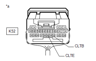
5. | INSPECT MAIN BODY ECU (MULTIPLEX NETWORK BODY ECU) |
|
*a | Component with harness connected (Main Body ECU (Multiplex Network Body ECU)) |
(a) Connect the K52 main body ECU (multiplex network body ECU) connector.
(b) Measure the voltage according to the value(s) in the table below.
Standard Voltage:
|
Tester Connection | Condition |
Specified Condition |
|---|---|---|
|
K52-23 (CLTB) - K52-25 (CLTE) |
Ignition switch off |
Below 1 V |
|
Ignition switch ON |
11 to 14 V |
| NG | |
REPLACE MAIN BODY ECU (MULTIPLEX NETWORK BODY ECU)
|
|
|
6. | INSPECT AUTOMATIC LIGHT CONTROL SENSOR |
(a) Inspect the automatic light control sensor.
Click here
| OK | |
REPLACE MAIN BODY ECU (MULTIPLEX NETWORK BODY ECU)
|
| NG | |
REPLACE AUTOMATIC LIGHT CONTROL SENSOR
|
READ NEXT:
 Automatic High Beam System (B124B)
DESCRIPTION The main body ECU (multiplex network body ECU) determines the status of the automatic high beam system based on the automatic high beam system signal from the forward recognition camera.
Automatic High Beam Camera (B124C)
DESCRIPTION The main body ECU (multiplex network body ECU) detects a high beam headlight illumination request signal of the automatic high beam system from the forward recognition camera.
DTC N
LED Headlight LH (B2430,B2431)
DESCRIPTION These DTCs are stored when the low beam headlights do not illuminate, or a communication malfunction is detected between the light control LED ECU and main body ECU (multiplex network body
SEE MORE:
Removal
REMOVAL CAUTION / NOTICE / HINT
The necessary procedures (adjustment, calibration, initialization, or registration) that must be performed after parts are removed and installed, or replaced during rack and pinion power steering gear assembly removal/installation are shown below. Necessary Procedu
Camshaft Position "A" - Timing Over-Advanced or System Performance Bank 1 Mechanical Failure (P001107,P002107)
DESCRIPTION Refer to DTC P001013. Click here
DTC No. Detection Item
DTC Detection Condition Trouble Area
MIL Memory
Note P001107
Camshaft Position "A" - Timing Over-Advanced or System Performance Bank 1 Mechanical Failure
10° CA or greater camshaft tim
