Toyota Camry (XV70): LED Headlight LH (B2430,B2431)
DESCRIPTION
These DTCs are stored when the low beam headlights do not illuminate, or a communication malfunction is detected between the light control LED ECU and main body ECU (multiplex network body ECU).
HINT:
DTC B2430 or DTC B2431 may also be stored if a headlight cooling fan is malfunctioning. In this case, the light control LED ECU will dim or turn off the malfunctioning low beam headlight.
|
DTC No. | Detection Item |
DTC Detection Condition |
Trouble Area | DTC Output from |
|---|---|---|---|---|
|
B2430 | LED Headlight LH | Detection condition:
|
| Main Body |
|
B2431 | LED Headlight RH | Detection condition:
|
| Main Body |
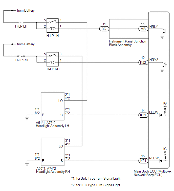
WIRING DIAGRAM
CAUTION / NOTICE / HINT
NOTICE:
- Inspect the fuses for circuits related to this system before performing the following procedure.
- Before replacing the main body ECU (multiplex network body ECU), refer to Registration.*
Click here
.gif)
- *: w/ Smart Key System
PROCEDURE
|
1. | CLEAR DTC |
(a) Connect the Techstream to the DLC3.
(b) Turn the ignition switch to ON.
(c) Turn the Techstream on.
(d) Enter the following menus: Body Electrical / Main Body / Trouble Codes.
(e) Clear the DTCs.
Body Electrical > Main Body > Clear DTCs
|
.gif)
|
2. | CHECK FOR DTC |
(a) Connect the Techstream to the DLC3.
(b) Start the engine.
(c) Operate the light control switch to turn on the low beam headlights and wait 10 seconds or more.
(d) Turn the Techstream on.
(e) Enter the following menus: Body Electrical / Main Body / Trouble Codes.
(f) Check for DTCs.
Body Electrical > Main Body > Trouble CodesOK:
DTC B2430 and B2431 are not output.
|
Result | Proceed to |
|---|---|
|
OK | A |
|
NG (DTC B2430 is output) |
B |
| NG (DTC B2431 is output) |
C |
| A | .gif) |
USE SIMULATION METHOD TO CHECK |
| C | |
GO TO STEP 12 |
|
|
3. | INSPECT HEADLIGHT ASSEMBLY LH (LO TERMINAL VOLTAGE) |
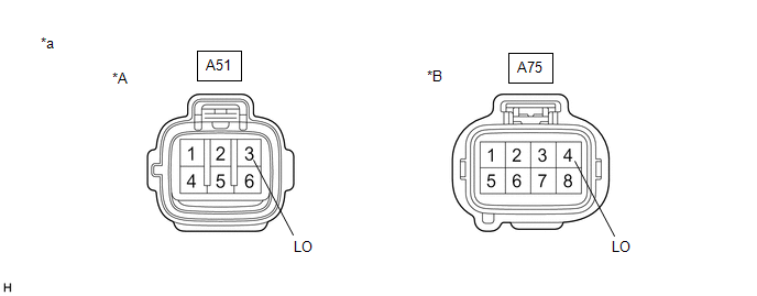
|
*A | for Bulb Type Turn Signal Light |
*B | for LED Type Turn Signal Light |
|
*a | Front view of wire harness connector (to Headlight Assembly LH) |
- | - |
(a) Disconnect the A51*1 or A75*2 headlight assembly LH connector.
- *1: for Bulb Type Turn Signal Light
- *2: for LED Type Turn Signal Light
(b) Measure the voltage according to the value(s) in the table below.
Standard Voltage:
for Bulb Type Turn Signal Light|
Tester Connection | Condition |
Specified Condition |
|---|---|---|
|
A51-3 (LO) - Body ground |
Light control switch in head position |
11 to 14 V |
|
Tester Connection | Condition |
Specified Condition |
|---|---|---|
|
A75-4 (LO) - Body ground |
Light control switch in head position |
11 to 14 V |
| NG | |
GO TO STEP 7 |
|
|
4. | CHECK HARNESS AND CONNECTOR (HEADLIGHT ASSEMBLY LH - BODY GROUND) |
(a) Measure the resistance according to the value(s) in the table below.
Standard Resistance:
for Bulb Type Turn Signal Light|
Tester Connection | Condition |
Specified Condition |
|---|---|---|
|
A51-1 (E) - Body ground |
Always | Below 1 Ω |
|
Tester Connection | Condition |
Specified Condition |
|---|---|---|
|
A75-8 (E) - Body ground |
Always | Below 1 Ω |
| NG | |
REPAIR OR REPLACE HARNESS OR CONNECTOR |
|
|
5. | INSPECT HEADLIGHT ASSEMBLY LH (S TERMINAL VOLTAGE) |

|
*A | for Bulb Type Turn Signal Light |
*B | for LED Type Turn Signal Light |
|
*a | Front view of wire harness connector (to Headlight Assembly LH) |
- | - |
(a) Measure the voltage according to the value(s) in the table below.
Standard Voltage:
for Bulb Type Turn Signal Light|
Tester Connection | Condition |
Specified Condition |
|---|---|---|
|
A51-2 (S) - Body ground |
Ignition switch ON |
11 to 14 V |
|
Tester Connection | Condition |
Specified Condition |
|---|---|---|
|
A75-7 (S) - Body ground |
Ignition switch ON |
11 to 14 V |
| OK | |
REPLACE HEADLIGHT ASSEMBLY LH |
|
|
6. | CHECK HARNESS AND CONNECTOR (HEADLIGHT ASSEMBLY LH - MAIN BODY ECU (MULTIPLEX NETWORK BODY ECU)) |
(a) Disconnect the K51 main body ECU (multiplex network body ECU) connector.
(b) Measure the resistance according to the value(s) in the table below.
Standard Resistance:
for Bulb Type Turn Signal Light|
Tester Connection | Condition |
Specified Condition |
|---|---|---|
|
A51-2 (S) - K51-14 (LLEW) |
Always | Below 1 Ω |
|
A51-2 (S) or K51-14 (LLEW) - Body ground |
Always | 10 kΩ or higher |
|
Tester Connection | Condition |
Specified Condition |
|---|---|---|
|
A75-7 (S) - K51-14 (LLEW) |
Always | Below 1 Ω |
|
A75-7 (S) or K51-14 (LLEW) - Body ground |
Always | 10 kΩ or higher |
| OK | |
REPLACE MAIN BODY ECU (MULTIPLEX NETWORK BODY ECU)
|
| NG | |
REPAIR OR REPLACE HARNESS OR CONNECTOR |
|
7. | CHECK HARNESS AND CONNECTOR (H-LP LH RELAY - HEADLIGHT ASSEMBLY LH) |
(a) Remove the H-LP LH relay.
(b) Measure the resistance according to the value(s) in the table below.
Standard Resistance:
for Bulb Type Turn Signal Light|
Tester Connection | Condition |
Specified Condition |
|---|---|---|
|
3 (H-LP LH relay) - A51-3 (LO) |
Always | Below 1 Ω |
|
3 (H-LP LH relay) or A51-3 (LO) - Body ground |
Always | 10 kΩ or higher |
|
Tester Connection | Condition |
Specified Condition |
|---|---|---|
|
3 (H-LP LH relay) - A75-4 (LO) |
Always | Below 1 Ω |
|
3 (H-LP LH relay) or A75-4 (LO) - Body ground |
Always | 10 kΩ or higher |
| NG | |
REPAIR OR REPLACE HARNESS OR CONNECTOR |
|
|
8. | INSPECT H-LP LH RELAY |
(a) Inspect the H-LP LH relay.
Click here
| NG | |
REPLACE H-LP LH RELAY |
|
|
9. | CHECK HARNESS AND CONNECTOR (POWER SOURCE - H-LP LH RELAY) |
(a) Measure the voltage according to the value(s) in the table below.
Standard Voltage:
|
Tester Connection | Condition |
Specified Condition |
|---|---|---|
|
2 (H-LP LH relay) - Body ground |
Always | 11 to 14 V |
|
5 (H-LP LH relay) - Body ground |
Always | 11 to 14 V |
| NG | |
REPAIR OR REPLACE HARNESS OR CONNECTOR |
|
|
10. | CHECK HARNESS AND CONNECTOR (H-LP LH RELAY - INSTRUMENT PANEL JUNCTION BLOCK ASSEMBLY) |
(a) Disconnect the 3C instrument panel junction block assembly connector.
(b) Measure the resistance according to the value(s) in the table below.
Standard Resistance:
|
Tester Connection | Condition |
Specified Condition |
|---|---|---|
|
1 (H-LP LH relay) - 3C-31 |
Always | Below 1 Ω |
|
1 (H-LP LH relay) or 3C-31 - Body ground |
Always | 10 kΩ or higher |
| NG | |
REPAIR OR REPLACE HARNESS OR CONNECTOR |
|
|
11. | INSPECT INSTRUMENT PANEL JUNCTION BLOCK ASSEMBLY |
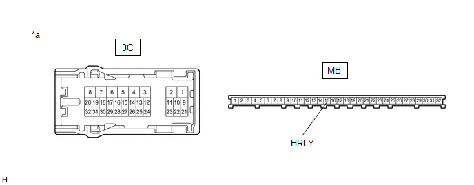
|
*a | Component without harness connected (Instrument Panel Junction Block Assembly) |
- | - |
(a) Remove the instrument panel junction block assembly.
Click here
(b) Remove the main body ECU (multiplex network body ECU) from the instrument panel junction block assembly.
(c) Measure the resistance according to the value(s) in the table below.
Standard Resistance:
|
Tester Connection | Condition |
Specified Condition |
|---|---|---|
|
3C-31 - MB-15 (HRLY) |
Always | Below 1 Ω |
| OK | |
REPLACE MAIN BODY ECU (MULTIPLEX NETWORK BODY ECU)
|
| NG | |
REPLACE INSTRUMENT PANEL JUNCTION BLOCK ASSEMBLY
|
|
12. | INSPECT HEADLIGHT ASSEMBLY RH (LO TERMINAL VOLTAGE) |

|
*A | for Bulb Type Turn Signal Light |
*B | for LED Type Turn Signal Light |
|
*a | Front view of wire harness connector (to Headlight Assembly RH) |
- | - |
(a) Disconnect the A50*1 or A74*2 headlight assembly RH connector.
- *1: for Bulb Type Turn Signal Light
- *2: for LED Type Turn Signal Light
(b) Measure the voltage according to the value(s) in the table below.
Standard Voltage:
for Bulb Type Turn Signal Light|
Tester Connection | Condition |
Specified Condition |
|---|---|---|
|
A50-3 (LO) - Body ground |
Light control switch in head position |
11 to 14 V |
|
Tester Connection | Condition |
Specified Condition |
|---|---|---|
|
A74-4 (LO) - Body ground |
Light control switch in head position |
11 to 14 V |
| NG | |
GO TO STEP 16 |
|
|
13. | CHECK HARNESS AND CONNECTOR (HEADLIGHT ASSEMBLY RH - BODY GROUND) |
(a) Measure the resistance according to the value(s) in the table below.
Standard Resistance:
for Bulb Type Turn Signal Light|
Tester Connection | Condition |
Specified Condition |
|---|---|---|
|
A50-1 (E) - Body ground |
Always | Below 1 Ω |
|
Tester Connection | Condition |
Specified Condition |
|---|---|---|
|
A74-8 (E) - Body ground |
Always | Below 1 Ω |
| NG | |
REPAIR OR REPLACE HARNESS OR CONNECTOR |
|
|
14. | INSPECT HEADLIGHT ASSEMBLY RH (S TERMINAL VOLTAGE) |
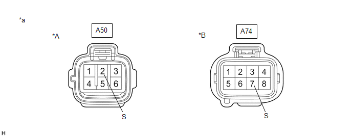
|
*A | for Bulb Type Turn Signal Light |
*B | for LED Type Turn Signal Light |
|
*a | Front view of wire harness connector (to Headlight Assembly RH) |
- | - |
(a) Measure the voltage according to the value(s) in the table below.
Standard Voltage:
for Bulb Type Turn Signal Light|
Tester Connection | Condition |
Specified Condition |
|---|---|---|
|
A50-2 (S) - Body ground |
Ignition switch ON |
11 to 14 V |
|
Tester Connection | Condition |
Specified Condition |
|---|---|---|
|
A74-7 (S) - Body ground |
Ignition switch ON |
11 to 14 V |
| OK | |
REPLACE HEADLIGHT ASSEMBLY RH |
|
|
15. | CHECK HARNESS AND CONNECTOR (HEADLIGHT ASSEMBLY RH - MAIN BODY ECU (MULTIPLEX NETWORK BODY ECU)) |
(a) Disconnect the K51 main body ECU (multiplex network body ECU) connector.
(b) Measure the resistance according to the value(s) in the table below.
Standard Resistance:
for Bulb Type Turn Signal Light|
Tester Connection | Condition |
Specified Condition |
|---|---|---|
|
A50-2 (S) - K51-15 (RLEW) |
Always | Below 1 Ω |
|
A50-2 (S) or K51-15 (RLEW) - Body ground |
Always | 10 kΩ or higher |
|
Tester Connection | Condition |
Specified Condition |
|---|---|---|
|
A74-7 (S) - K51-15 (RLEW) |
Always | Below 1 Ω |
|
A74-7 (S) or K51-15 (RLEW) - Body ground |
Always | 10 kΩ or higher |
| OK | |
REPLACE MAIN BODY ECU (MULTIPLEX NETWORK BODY ECU)
|
| NG | |
REPAIR OR REPLACE HARNESS OR CONNECTOR |
|
16. | CHECK HARNESS AND CONNECTOR (H-LP RH RELAY - HEADLIGHT ASSEMBLY RH) |
(a) Remove the H-LP RH relay.
(b) Measure the resistance according to the value(s) in the table below.
Standard Resistance:
for Bulb Type Turn Signal Light|
Tester Connection | Condition |
Specified Condition |
|---|---|---|
|
3 (H-LP RH relay) - A50-3 (LO) |
Always | Below 1 Ω |
|
3 (H-LP RH relay) or A50-3 (LO) - Body ground |
Always | 10 kΩ or higher |
|
Tester Connection | Condition |
Specified Condition |
|---|---|---|
|
3 (H-LP RH relay) - A74-4 (LO) |
Always | Below 1 Ω |
|
3 (H-LP RH relay) or A74-4 (LO) - Body ground |
Always | 10 kΩ or higher |
| NG | |
REPAIR OR REPLACE HARNESS OR CONNECTOR |
|
|
17. | INSPECT H-LP RH RELAY |
(a) Inspect the H-LP RH relay.
Click here
| NG | |
REPLACE H-LP RH RELAY |
|
|
18. | CHECK HARNESS AND CONNECTOR (POWER SOURCE - H-LP RH RELAY) |
(a) Measure the voltage according to the value(s) in the table below.
Standard Voltage:
|
Tester Connection | Condition |
Specified Condition |
|---|---|---|
|
2 (H-LP RH relay) - Body ground |
Always | 11 to 14 V |
|
5 (H-LP RH relay) - Body ground |
Always | 11 to 14 V |
| NG | |
REPAIR OR REPLACE HARNESS OR CONNECTOR |
|
|
19. | CHECK HARNESS AND CONNECTOR (H-LP RH RELAY - MAIN BODY ECU (MULTIPLEX NETWORK BODY ECU)) |
(a) Disconnect the K52 main body ECU (multiplex network body ECU) connector.
(b) Measure the resistance according to the value(s) in the table below.
Standard Resistance:
|
Tester Connection | Condition |
Specified Condition |
|---|---|---|
|
1 (H-LP RH relay) - K52-12 (HRY2) |
Always | Below 1 Ω |
|
1 (H-LP RH relay) or K52-12 (HRY2) - Body ground |
Always | 10 kΩ or higher |
| OK | |
REPLACE MAIN BODY ECU (MULTIPLEX NETWORK BODY ECU)
|
| NG | |
REPAIR OR REPLACE HARNESS OR CONNECTOR |
READ NEXT:
 Lost Communication With ECM/PCM "A" (U0100,U0101,U0120,U0126,U0129,U0151,U0155,U0163,U0164,U023A,U0327,U1106,U1117)
DESCRIPTION These DTCs are stored if a CAN communication malfunction occurs between the main body ECU (multiplex network body ECU) and other ECUs.
DTC No. Detection Item
DTC Detection C
Lost Communication With ECM/PCM "A" Missing Message (U010087,U012587,U012987,U014087)
DESCRIPTION These DTCs are stored if a CAN communication malfunction occurs between the forward recognition camera and other ECUs.
DTC No. Detection Item
DTC Detection Condition
T
Lost Communication with Cruise Control Front Distance Range Sensor Signal Sensor or Center Missing Message (U023587)
DESCRIPTION The forward recognition camera and millimeter wave radar sensor assembly communicate via CAN communication. If there is an error in the communication with the millimeter wave radar sensor
SEE MORE:
Replacement
REPLACEMENT PROCEDURE 1. REPLACE STRAIGHT PIN
NOTICE: If a straight pin is deformed, replace it. (a) Using a plastic hammer, tap in new straight pins to the cylinder block sub-assembly.
*a Front Side
*b Rear Side
*c Top Side
*d Bottom Side
*e RH Side
Removal
REMOVAL CAUTION / NOTICE / HINT
The necessary procedures (adjustment, calibration, initialization or registration) that must be performed after parts are removed and installed, or replaced during fuel injector assembly removal/installation are shown below. Necessary Procedures After Parts Removed/
