Toyota Camry (XV70): Parts Location
Toyota Camry Repair Manual XV70 (2018-2024) / Steering / Power Assist Systems / Power Steering System / Parts Location
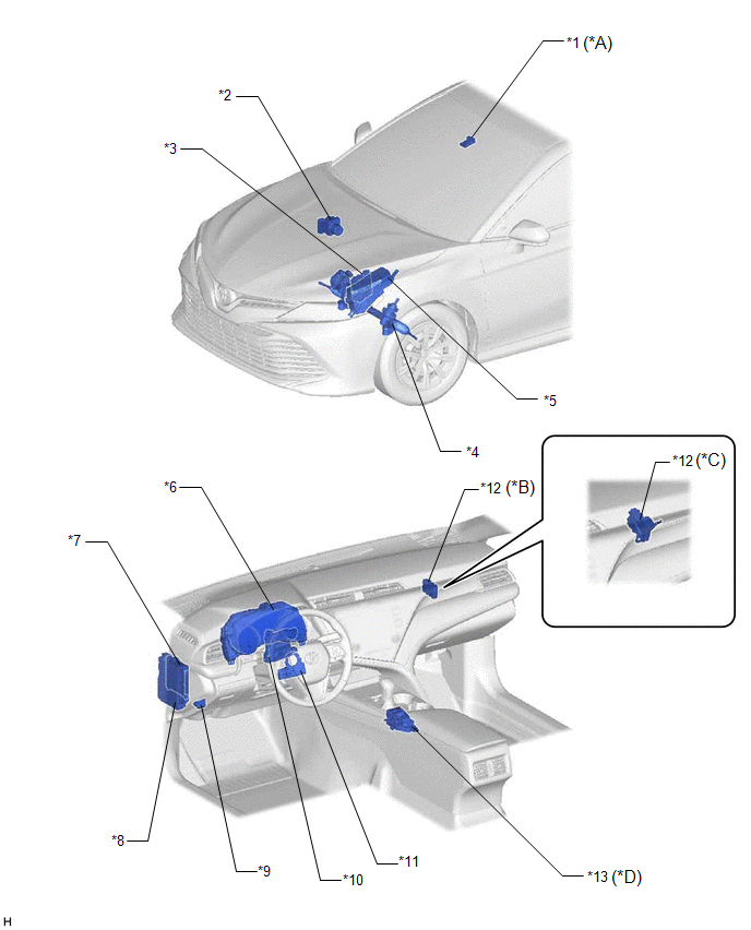
PARTS LOCATION
ILLUSTRATION
|
*A | w/ Forward Recognition Camera |
*B | w/ Smart Key System |
|
*C | w/o Smart Key System |
*D | w/ Drive Mode Switch |
|
*1 | FORWARD RECOGNITION CAMERA |
*2 | BRAKE ACTUATOR ASSEMBLY - SKID CONTROL ECU |
|
*3 | ECM |
*4 | RACK AND PINION POWER STEERING GEAR ASSEMBLY - POWER STEERING ECU - POWER STEERING MOTOR - TORQUE SENSOR |
|
*5 | ENGINE ROOM RELAY BLOCK AND JUNCTION BLOCK ASSEMBLY - EPS FUSE | *6 |
COMBINATION METER ASSEMBLY |
|
*7 | MAIN BODY ECU (MULTIPLEX NETWORK BODY ECU) |
*8 | INSTRUMENT PANEL JUNCTION BLOCK ASSEMBLY - IG1-NO. 1 RELAY - EPS-IG1 FUSE |
|
*9 | DLC3 |
*10 | AIR CONDITIONING AMPLIFIER ASSEMBLY |
|
*11 | STEERING SENSOR |
*12 | CENTRAL GATEWAY ECU (NETWORK GATEWAY ECU) |
|
*13 | DRIVE MODE SWITCH (ELECTRIC PARKING BRAKE SWITCH ASSEMBLY) |
- | - |
READ NEXT:
 System Diagram
SYSTEM DIAGRAM
System Description
SYSTEM DESCRIPTION DESCRIPTION (a) The power steering ECU (rack and pinion power steering gear assembly) generates the necessary steering assist torque by calculating the steering assist force and con
How To Proceed With Troubleshooting
CAUTION / NOTICE / HINT
HINT:
Use the following procedure to troubleshoot the power steering system.
*: Use the Techstream.
PROCEDURE
1. VEHICLE BROUGHT TO WORKSHOP
SEE MORE:
Inspection
INSPECTION PROCEDURE 1. INSPECT POWER WINDOW REGULATOR MOTOR ASSEMBLY (FOR REAR LH DOOR)
(a) Connect a positive (+) battery lead to connector terminal 2.
NOTICE: Do not connect a positive (+) battery lead to any terminals other than terminal 2 to avoid damaging the pulse sensor inside the
Removal
REMOVAL CAUTION / NOTICE / HINT
The necessary procedures (adjustment, calibration, initialization or registration) that must be performed after parts are removed and installed, or replaced during vacuum warning switch assembly removal/installation are shown below. Necessary Procedures After Parts
© 2023-2026 Copyright www.tocamry.com
