
Toyota Camry (XV70): System Diagram
Toyota Camry Repair Manual XV70 (2018-2024) / Steering / Power Assist Systems / Power Steering System / System Diagram
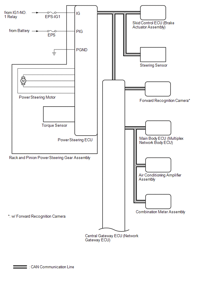
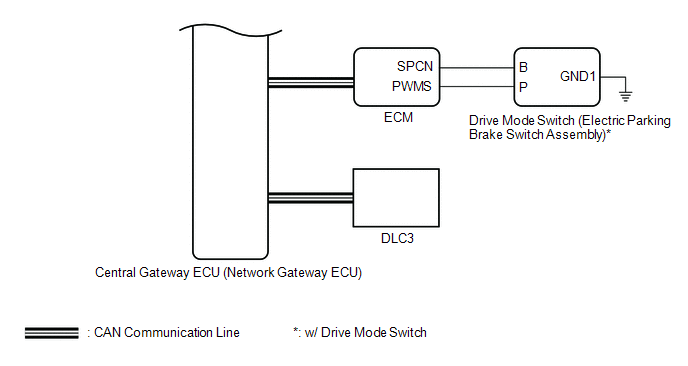
SYSTEM DIAGRAM
READ NEXT:
 System Description
SYSTEM DESCRIPTION DESCRIPTION (a) The power steering ECU (rack and pinion power steering gear assembly) generates the necessary steering assist torque by calculating the steering assist force and con
How To Proceed With Troubleshooting
CAUTION / NOTICE / HINT
HINT:
Use the following procedure to troubleshoot the power steering system.
*: Use the Techstream.
PROCEDURE
1. VEHICLE BROUGHT TO WORKSHOP
Calibration
CALIBRATION TORQUE SENSOR ZERO POINT CALIBRATION (USING TECHSTREAM)
NOTICE: Perform torque sensor zero point calibration if any of the following conditions occur:
The rack and pinion power s
SEE MORE:
Brake Switch "A" Circuit Short to Battery (P057112)
DESCRIPTION The skid control ECU (brake actuator assembly) receives stop light switch assembly signals and uses them to determine whether or not the brakes are applied.
DTCs may be stored if either of the following occurs:
Stop light switch assembly stuck on malfunction.
The accelerator a
Inspection
INSPECTION PROCEDURE 1. INSPECT FUEL INJECTOR ASSEMBLY
(a) Check the resistance.
(1) Measure the resistance according to the value(s) in the table below.
Standard Resistance:
Tester Connection Condition
Specified Condition 1 - 2
20°C (68°F) 11.6 to 12.4 ]
© 2023-2026 Copyright www.tocamry.com
