Toyota Camry (XV70): Parts Location
PARTS LOCATION
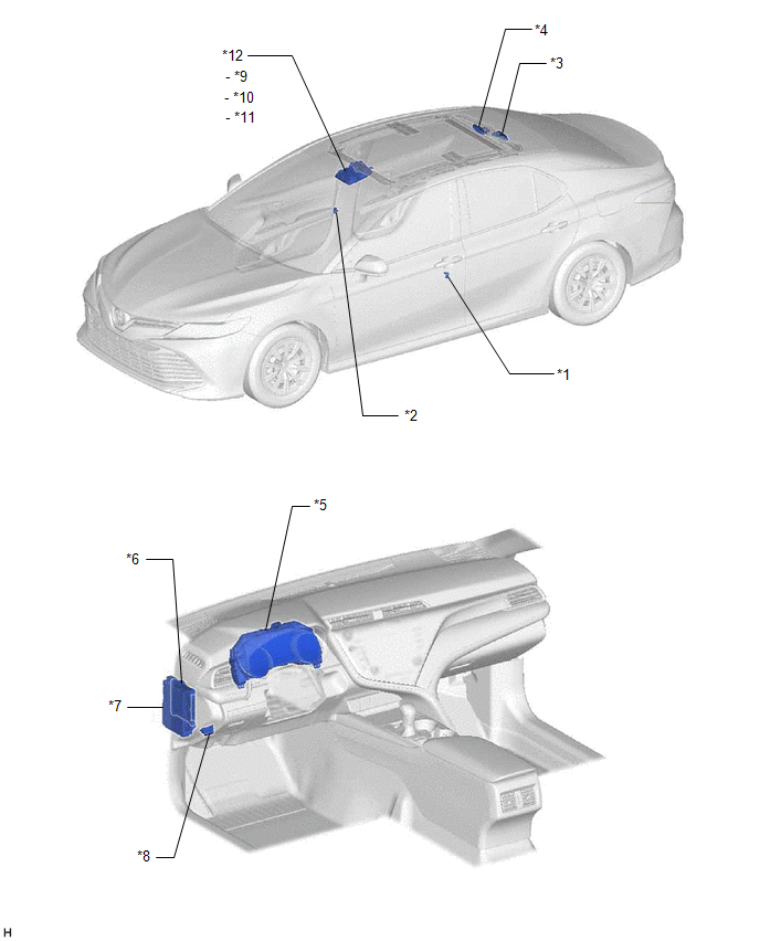
ILLUSTRATION
|
*1 | FRONT DOOR COURTESY LIGHT SWITCH ASSEMBLY (for LH) |
*2 | FRONT DOOR COURTESY LIGHT SWITCH ASSEMBLY (for RH) |
|
*3 | SLIDING ROOF ECU (SLIDING ROOF DRIVE GEAR ASSEMBLY) |
*4 | ROOF SUNSHADE ECU (SLIDING ROOF DRIVE GEAR ASSEMBLY) |
|
*5 | COMBINATION METER ASSEMBLY |
*6 | MAIN BODY ECU (MULTIPLEX NETWORK BODY ECU) |
|
*7 | INSTRUMENT PANEL JUNCTION BLOCK ASSEMBLY - ECU-IG1 NO. 3 FUSE - S/ROOF FUSE |
*8 | DLC3 |
|
*9 | SLIDING ROOF SWITCH |
*10 | ROOF SUNSHADE SWITCH |
|
*11 | TILT SWITCH |
*12 | PANORAMIC MOON ROOF SWITCH (ROOF CONSOLE BOX SUB-ASSEMBLY) |
READ NEXT:
 System Diagram
SYSTEM DIAGRAM
Communication Table
Sender Receiver
Signal Line
Main Body ECU (Multiplex Network Body ECU)
Sliding Roof ECU (Sliding Roof Drive Gear Assembly)
System Description
SYSTEM DESCRIPTION PANORAMIC MOON ROOF SYSTEM DESCRIPTION
(a) The panoramic moon roof system controls the sliding roof operation using the sliding roof ECU (sliding roof drive gear assembly) and ro
How To Proceed With Troubleshooting
CAUTION / NOTICE / HINT
HINT:
Use the following procedure to troubleshoot the panoramic moon roof system.
*: Use the Techstream.
PROCEDURE
1. VEHICLE BROUGHT TO WORKSHOP
SEE MORE:
Removal
REMOVAL PROCEDURE 1. REMOVE FRONT WHEEL RH
Click here 2. REMOVE FRONT FENDER APRON SEAL RH
Click here
3. REMOVE V-BANK COVER SUB-ASSEMBLY Click here
4. REMOVE CAMSHAFT TIMING OIL CONTROL SOLENOID ASSEMBLY (for Exhaust Side of Bank 2)
Click here 5. SET NO. 1 CYLINDER
Lost Communication with Cruise Control Module Missing Message (U010487)
DESCRIPTION The millimeter wave radar sensor assembly communicates with the forward recognition camera via CAN communication.
If a communication error is detected between the forward recognition camera and millimeter wave radar sensor assembly, the millimeter wave radar sensor assembly stores this
© 2023-2026 Copyright www.tocamry.com
