Toyota Camry (XV70): Parts Location
Toyota Camry Repair Manual XV70 (2018-2024) / Vehicle Exterior / Sliding Roof / Convertible / Sliding Roof System / Parts Location
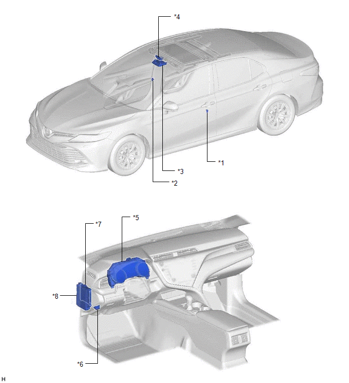
PARTS LOCATION
ILLUSTRATION
|
*1 | FRONT DOOR COURTESY LIGHT SWITCH ASSEMBLY (for LH) |
*2 | FRONT DOOR COURTESY LIGHT SWITCH ASSEMBLY (for RH) |
|
*3 | SLIDING ROOF SWITCH (ROOF CONSOLE BOX SUB-ASSEMBLY) |
*4 | SLIDING ROOF ECU (SLIDING ROOF DRIVE GEAR SUB-ASSEMBLY) |
|
*5 | COMBINATION METER ASSEMBLY |
*6 | DLC3 |
|
*7 | MAIN BODY ECU (MULTIPLEX NETWORK BODY ECU) |
*8 | INSTRUMENT PANEL JUNCTION BLOCK ASSEMBLY - S/ROOF FUSE - ECU-IG1 NO. 3 FUSE |
READ NEXT:
 System Diagram
SYSTEM DIAGRAM
Communication Table
Sender Receiver
Signal Line
Main Body ECU (Multiplex Network Body ECU)
Sliding Roof ECU (Sliding Roof Drive Gear Sub-assembly)
System Description
SYSTEM DESCRIPTION SLIDING ROOF SYSTEM DESCRIPTION
(a) The sliding roof system controls the sliding roof operation using the sliding roof ECU (sliding roof drive gear sub-assembly). Operating the s
How To Proceed With Troubleshooting
CAUTION / NOTICE / HINT
HINT:
Use the following procedure to troubleshoot the sliding roof system.
*: Use the Techstream.
PROCEDURE
1. VEHICLE BROUGHT TO WORKSHOP
SEE MORE:
Actuator Supply Voltage "A" Circuit Short to Ground or Open (P065714)
DESCRIPTION The electronic throttle control system has a dedicated power supply circuit. The voltage (+BM) is monitored and when it is low (less than 4 V), the ECM determines that there is a malfunction in the electronic throttle control system and cuts off the current to the throttle actuator.
Wh
Lost Communication with Brake System Control Module Missing Message (U012987)
MONITOR DESCRIPTION The ECM and skid control ECU (brake actuator assembly) send and receive signals via CAN communication.
If a communication error occurs between the ECM and skid control ECU (brake actuator assembly), the ECM stores this DTC.
DTC No. Detection Item
DTC Detection Cond
© 2023-2026 Copyright www.tocamry.com
