Toyota Camry (XV70): System Diagram
Toyota Camry Repair Manual XV70 (2018-2024) / Vehicle Exterior / Sliding Roof / Convertible / Sliding Roof System / System Diagram
SYSTEM DIAGRAM
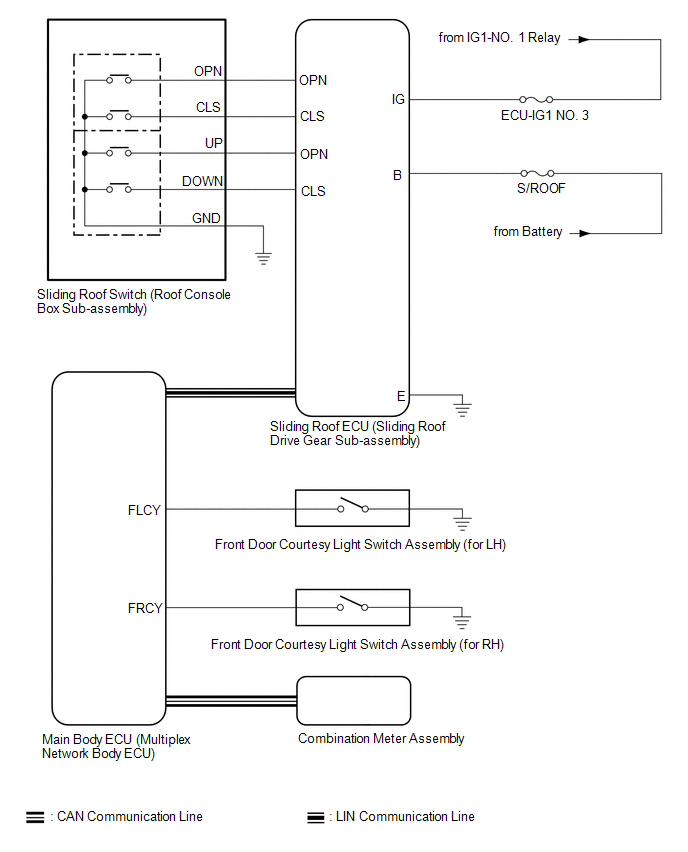 Communication Table
 |
Sender | Receiver |
Signal | Line |
|---|---|---|---|
|
Main Body ECU (Multiplex Network Body ECU) |
Sliding Roof ECU (Sliding Roof Drive Gear Sub-assembly) |
| LIN |
|
Sliding Roof ECU (Sliding Roof Drive Gear Sub-assembly) |
Main Body ECU (Multiplex Network Body ECU) |
Sliding roof position signal |
LIN |
| Combination Meter Assembly |
Main Body ECU (Multiplex Network Body ECU) |
Vehicle speed signal |
CAN |
| Main Body ECU (Multiplex Network Body ECU) |
Combination Meter Assembly | Sliding roof open warning request signal |
CAN |
READ NEXT:
 System Description
SYSTEM DESCRIPTION SLIDING ROOF SYSTEM DESCRIPTION
(a) The sliding roof system controls the sliding roof operation using the sliding roof ECU (sliding roof drive gear sub-assembly). Operating the s
How To Proceed With Troubleshooting
CAUTION / NOTICE / HINT
HINT:
Use the following procedure to troubleshoot the sliding roof system.
*: Use the Techstream.
PROCEDURE
1. VEHICLE BROUGHT TO WORKSHOP
Operation Check
OPERATION CHECK CHECK AUTO OPERATION FUNCTION
NOTICE:
Make sure that initialization has been completed before performing this inspection.
Click here
The sliding roof auto operation ca
SEE MORE:
Light bulbs
You may replace the following bulbs yourself. The difficulty level
of replacement varies depending on the bulb. If necessary bulb
replacement seems difficult to perform, contact your Toyota
dealer.
For more information about replacing other light bulbs, contact
your Toyota dealer.
Preparing
Lost Communication with ECM/PCM "A" Missing Message (U010087,U012587,U012987,U014087,U015587)
DESCRIPTION When a malfunction is detected between various ECUs and sensors, these DTCs are stored.
DTC No. Detection Item
DTC Detection Condition Trouble Area
U010087 Lost Communication with ECM/PCM "A" Missing Message
3 seconds or more after the ignition switch to ON
© 2023-2026 Copyright www.tocamry.com
