
Toyota Camry (XV70): Parts Location
PARTS LOCATION
ILLUSTRATION
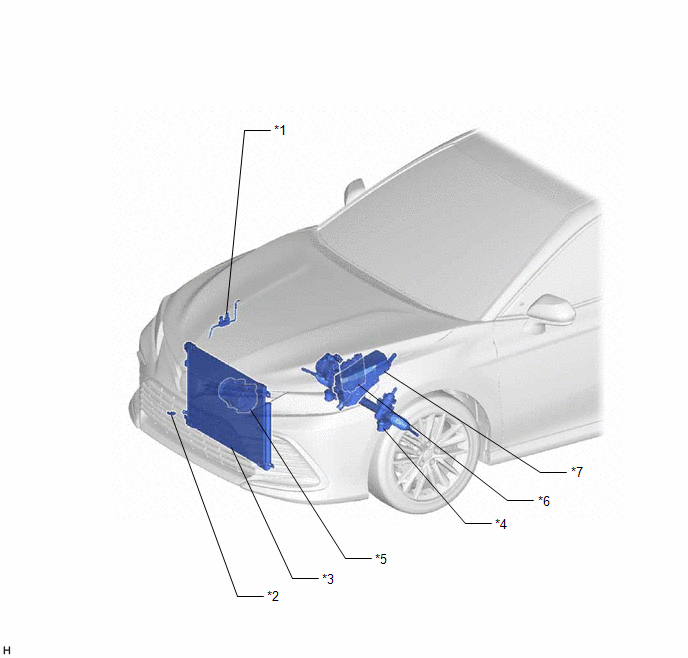
|
*1 | AIR CONDITIONER PRESSURE SENSOR |
*2 | THERMISTOR ASSEMBLY |
|
*3 | COOLER CONDENSER ASSEMBLY |
*4 | RACK AND PINION POWER STEERING GEAR ASSEMBLY (POWER STEERING ECU) |
|
*5 | COMPRESSOR ASSEMBLY WITH PULLEY (COMPRESSOR SOLENOID) |
*6 | ECM |
|
*7 | ENGINE ROOM RELAY BLOCK AND JUNCTION BLOCK ASSEMBLY - HTR FUSE | - |
- |
ILLUSTRATION
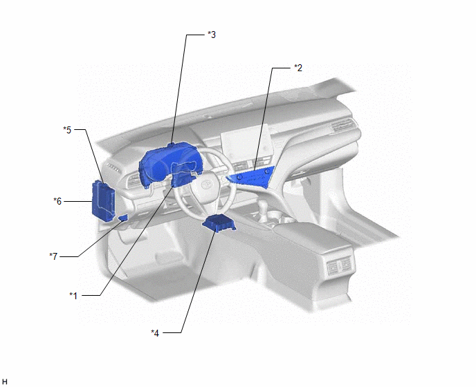
|
*1 | AIR CONDITIONING AMPLIFIER ASSEMBLY |
*2 | AIR CONDITIONING CONTROL ASSEMBLY |
|
*3 | COMBINATION METER ASSEMBLY |
*4 | AIRBAG SENSOR ASSEMBLY |
|
*5 | MAIN BODY ECU (MULTIPLEX NETWORK BODY ECU) |
*6 | INSTRUMENT PANEL JUNCTION BLOCK ASSEMBLY - ECU-B NO. 2 FUSE - ECU-IG1 NO. 4 FUSE |
|
*7 | DLC3 |
- | - |
ILLUSTRATION
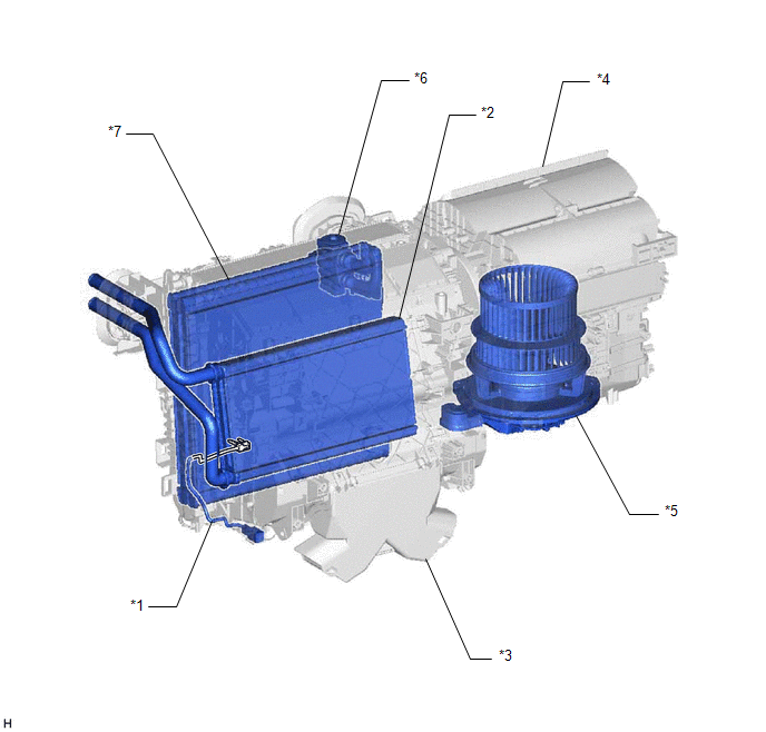
|
*1 | NO. 1 COOLER THERMISTOR |
*2 | HEATER RADIATOR UNIT SUB-ASSEMBLY |
|
*3 | AIR CONDITIONING RADIATOR ASSEMBLY |
*4 | BLOWER ASSEMBLY |
|
*5 | BLOWER MOTOR WITH FAN SUB-ASSEMBLY |
*6 | COOLER EXPANSION VALVE |
|
*7 | NO. 1 COOLER EVAPORATOR SUB-ASSEMBLY |
- | - |
ILLUSTRATION
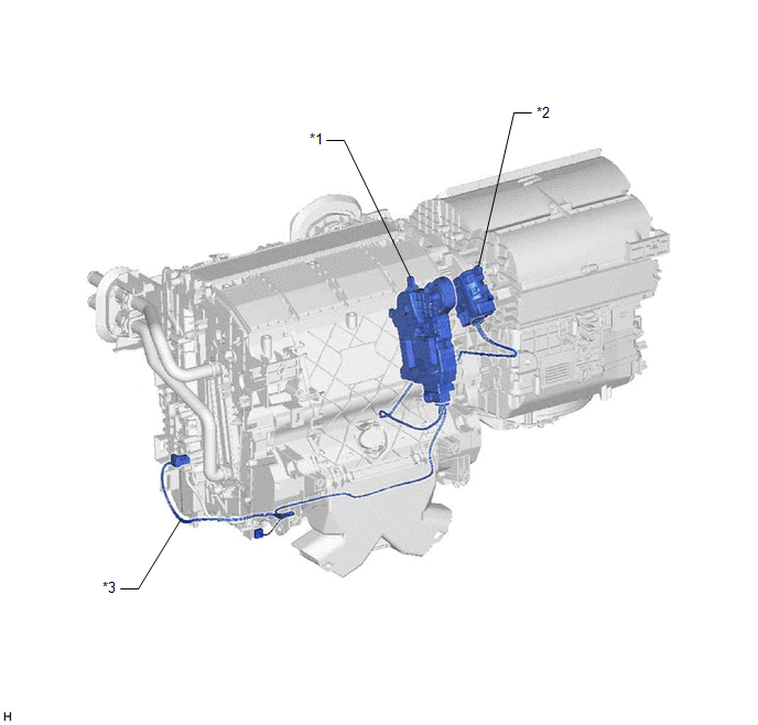
|
*1 | NO. 1 AIR CONDITIONING RADIATOR DAMPER SERVO SUB-ASSEMBLY |
*2 | NO. 1 BLOWER DAMPER SERVO SUB-ASSEMBLY |
|
*3 | AIR CONDITIONING HARNESS ASSEMBLY |
- | - |
READ NEXT:
 System Diagram
SYSTEM DIAGRAM
System Description
SYSTEM DESCRIPTION COMMUNICATION SYSTEM FUNCTION
(a) The air conditioning amplifier assembly communicates with each ECU via CAN communication and LIN communication. Additionally, the air conditioning
How To Proceed With Troubleshooting
CAUTION / NOTICE / HINT
HINT:
Use the following procedure to troubleshoot the air conditioning system.
*: Use the Techstream.
PROCEDURE
1. VEHICLE BROUGHT TO WORKSHOP
NEX
SEE MORE:
Removal
REMOVAL CAUTION / NOTICE / HINT
The necessary procedures (adjustment, calibration, initialization, or registration) that must be performed after parts are removed and installed, or replaced during steering column assembly removal/installation are shown below. Necessary Procedures After Parts Remo
Installation
INSTALLATION PROCEDURE 1. INSTALL AUTOMATIC LIGHT CONTROL SENSOR
(a) Engage the 2 claws to install the automatic light control sensor. (b) Connect the connector.
2. INSTALL DEFROSTER NOZZLE ASSEMBLY Click here
3. INSTALL NO. 2 SIDE DEFROSTER NOZZLE DUCT Click here
4. INSTALL NO. 1
