Toyota Camry (XV70): Radio Broadcast cannot be Received or Poor Reception
CAUTION / NOTICE / HINT
NOTICE:
- Depending on the parts that are replaced during vehicle inspection or maintenance, performing initialization, registration or calibration may be needed. Refer to Precaution for Audio and Visual System.
Click here
.gif)
- When replacing the radio and display receiver assembly, always replace it with a new one. If a radio and display receiver assembly which was installed to another vehicle is used, the following may occur:
- A communication malfunction DTC may be stored.
- The radio and display receiver assembly may not operate normally.
PROCEDURE
|
1. | CHECK RADIO AND DISPLAY RECEIVER ASSEMBLY |
(a) Check the radio automatic station search function.
(1) Check the radio automatic station search function by activating it.
|
Result | Proceed to |
|---|---|
|
Automatic station search function does not stop. |
A |
| Automatic station search function stops on a station. |
B |
| B |
.gif) | REPLACE RADIO AND DISPLAY RECEIVER ASSEMBLY
|
|
.gif)
| 2. |
CHECK OPTIONAL COMPONENTS |
(a) Check if any optional components that may decrease reception capacity, such as a sunshade film or telephone antenna, are installed.
|
Result | Proceed to |
|---|---|
|
Optional components are not installed. |
A |
| Optional components are installed. |
B |
NOTICE:
Do not remove optional components without the permission of the customer.
| B |
| REMOVE OPTIONAL COMPONENTS AND CHECK AGAIN (SEE NOTICE ABOVE) |
|
| 3. |
CHECK RADIO AND DISPLAY RECEIVER ASSEMBLY |
| (a) Preparation for check (1) Disconnect the antenna connector from the radio and display receiver assembly. |
|
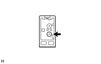
(b) Check for noise
(1) Turn the ignition switch to ACC with the radio and display receiver assembly connector connected.
(2) Turn the radio on and tune into AM mode.
(3) Place a screwdriver, thin wire or other metal object on the radio and display receiver assembly antenna jack and check that noise can be heard from the speakers.
OK:
Noise can be heard from the speakers.
| NG | | REPLACE RADIO AND DISPLAY RECEIVER ASSEMBLY
|
|
| 4. |
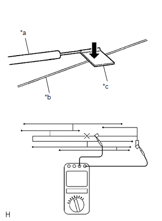
CHECK WINDOW GLASS ANTENNA WIRE |
| (a) Check for continuity in the window glass antenna wire. NOTICE: When cleaning the glass, wipe it in the direction of the wire with a soft dry cloth. Take care not to damage the wire. Do not use detergents or glass cleaners with abrasive ingredients. When measuring resistance, wrap a piece of tin foil around the tip of each probe and press the foil against the wire with your finger, as shown in the illustration. HINT: Check for continuity at the center of each antenna wire as shown in the illustration. OK: There is continuity in the window glass antenna wire. |
|
| NG | | REPAIR WINDOW GLASS ANTENNA WIRE |
|
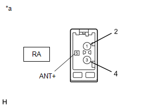
| 5. |
INSPECT RADIO AND DISPLAY RECEIVER ASSEMBLY |
(a) Disconnect the RA radio and display receiver assembly connector.
| (b) Measure the voltage according to the value(s) in the table below. Standard Voltage:
|
|
| NG | | REPLACE RADIO AND DISPLAY RECEIVER ASSEMBLY
|
|
| 6. |
REPLACE ANTENNA CORD SUB-ASSEMBLY (for Front Side) |
(a) Replace the antenna cord sub-assembly (for front side) with a new or known good one and check if radio broadcasts can be received normally.
Click here
OK:
Radio broadcasts can be received normally.
| OK | | END |
|
| 7. |
REPLACE NO. 2 ANTENNA CORD SUB-ASSEMBLY |
(a) Replace the No. 2 antenna cord sub-assembly with a new or known good one and check if radio broadcasts can be received normally.
Click here
OK:
Radio broadcasts can be received normally.
| OK | | END |
|
| 8. |
REPLACE NO. 1 AMPLIFIER ANTENNA ASSEMBLY |
(a) Replace the No. 1 amplifier antenna assembly with a new or known good one and check if radio broadcasts can be received normally.
Click here
OK:
Radio broadcasts can be received normally.
| OK | | END |
|
| 9. |
REPLACE ANTENNA CORD SUB-ASSEMBLY (for Rear Side) |
(a) Replace the antenna cord sub-assembly (for rear side) with a new or known good one and check if radio broadcasts can be received normally.
Click here
OK:
Radio broadcasts can be received normally.
| OK | | END |
| NG | | REPLACE RADIO AND DISPLAY RECEIVER ASSEMBLY
|
READ NEXT:
 Illumination for Panel Switch does not Come on with Tail Switch ON
CAUTION / NOTICE / HINT
NOTICE:
Depending on the parts that are replaced during vehicle inspection or maintenance, performing initialization, registration or calibration may be needed. Refer to
Display does not Dim when Light Control Switch is Turned ON
CAUTION / NOTICE / HINT
NOTICE:
Depending on the parts that are replaced during vehicle inspection or maintenance, performing initialization, registration or calibration may be needed. Refer to
Panel Switches do not Function
CAUTION / NOTICE / HINT
NOTICE:
Depending on the parts that are replaced during vehicle inspection or maintenance, performing initialization, registration or calibration may be needed. Refer to
SEE MORE:
Diagnostic Trouble Code Chart
DIAGNOSTIC TROUBLE CODE CHART SFI System
DTC No. Detection Item
MIL Memory
Note Link
P001013 A Camshaft Position Actuator Bank 1 Circuit Open
Comes on DTC stored
SAE Code: P0010
P001100 Camshaft Position "A" - Timing Over-Advanced or S
Components
COMPONENTS ILLUSTRATION
*1 FRONT DISC BRAKE ANTI-SQUEAL SHIM KIT
*2 FRONT DISC BRAKE PAD
*3 FRONT DISC BRAKE CYLINDER ASSEMBLY
*4 FRONT DISC BRAKE PAD WEAR INDICATOR PLATE
*5 FRONT NO. 1 DISC BRAKE ANTI-SQUEAL SHIM
*6 FRONT NO. 2 DISC BRAKE ANT
