Toyota Camry (XV70): Radio Receiver Power Source Circuit
DESCRIPTION
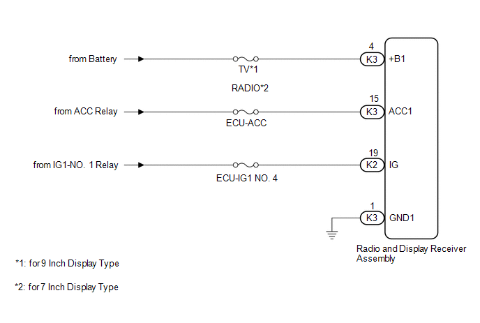
This is the power source circuit to operate the radio and display receiver assembly.
WIRING DIAGRAM
CAUTION / NOTICE / HINT
NOTICE:
Inspect the fuses for circuits related to this system before performing the following procedure.
PROCEDURE
| 1. |
CHECK HARNESS AND CONNECTOR (RADIO AND DISPLAY RECEIVER ASSEMBLY POWER SOURCE) |
(a) Disconnect the K3 and K2 radio and display receiver assembly connectors.
(b) Measure the resistance according to the value(s) in the table below.
Standard Resistance:
|
Tester Connection | Condition |
Specified Condition |
|---|---|---|
|
K3-1 (GND1) - Body ground |
Always | Below 1 Ω |
(c) Measure the voltage according to the value(s) in the table below.
Standard Voltage:
|
Tester Connection | Condition |
Specified Condition |
|---|---|---|
|
K3-4 (+B1) - K3-1 (GND1) |
Always | 11 to 14 V |
|
K3-15 (ACC1) - K3-1 (GND1) |
Ignition switch ACC | 11 to 14 V |
|
K2-19 (IG) - K3-1 (GND1) |
Ignition switch ON | 11 to 14 V |
| OK | .gif) | PROCEED TO NEXT SUSPECTED AREA SHOWN IN PROBLEM SYMPTOMS TABLE |
| NG | | REPAIR OR REPLACE HARNESS OR CONNECTOR |
READ NEXT:
 Components
COMPONENTS ILLUSTRATION
*A for Front Passenger Side
*B for Driver Side
*C w/o Courtesy Light
*D w/ Courtesy Light
*1 COURTESY LIGHT ASSEMBLY
*2
Removal
REMOVAL CAUTION / NOTICE / HINT
HINT:
Use the same procedure for the RH side and LH side.
The following procedure is for the LH side.
PROCEDURE 1. REMOVE FRONT DOOR LOWER FRAME BRACKET G
SEE MORE:
Parking Brake Switch Circuit
DESCRIPTION This circuit is from the skid control ECU (brake actuator assembly) to the radio and display receiver assembly. WIRING DIAGRAM
PROCEDURE
1.
CHECK BRAKE WARNING LIGHT (a) Check that the brake warning light comes on when the parking brake is applied and goes off when it is
Cooling Fan Circuit
DESCRIPTION The ECM calculates an appropriate cooling fan speed based on the engine coolant temperature, air conditioning switch status, refrigerant pressure, engine speed and vehicle speed, and sends a signal to the cooling fan ECU (fan with motor assembly). The cooling fan ECU (fan with motor asse
