Toyota Camry (XV70): Components
COMPONENTS
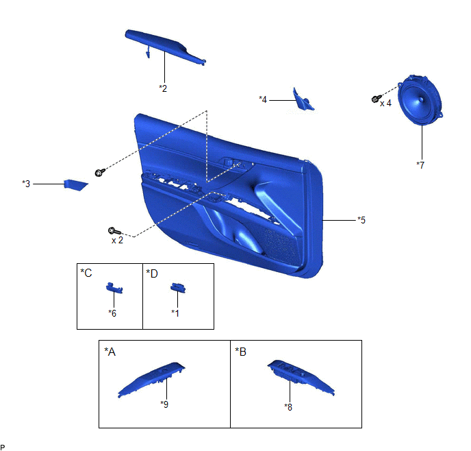
ILLUSTRATION
|
*A | for Front Passenger Side |
*B | for Driver Side |
|
*C | w/o Courtesy Light |
*D | w/ Courtesy Light |
|
*1 | COURTESY LIGHT ASSEMBLY |
*2 | FRONT ARMREST ASSEMBLY |
|
*3 | FRONT DOOR ARMREST COVER SUB-ASSEMBLY |
*4 | FRONT DOOR LOWER FRAME BRACKET GARNISH |
|
*5 | FRONT DOOR TRIM BOARD SUB-ASSEMBLY |
*6 | FRONT DOOR TRIM PLATE |
|
*7 | FRONT NO. 1 SPEAKER ASSEMBLY |
*8 | MULTIPLEX NETWORK MASTER SWITCH ASSEMBLY WITH FRONT DOOR UPPER ARMREST BASE PANEL |
|
*9 | POWER WINDOW REGULATOR SWITCH ASSEMBLY WITH FRONT DOOR UPPER ARMREST BASE PANEL |
- | - |
READ NEXT:
 Removal
REMOVAL CAUTION / NOTICE / HINT
HINT:
Use the same procedure for the RH side and LH side.
The following procedure is for the LH side.
PROCEDURE 1. REMOVE FRONT DOOR LOWER FRAME BRACKET G
Inspection
INSPECTION PROCEDURE 1. INSPECT FRONT NO. 1 SPEAKER ASSEMBLY
(a) With the speaker installed, check that there is no looseness or other abnormalities.
(b) Check that there is no foreign matter in t
Installation
INSTALLATION CAUTION / NOTICE / HINT
HINT:
Use the same procedure for the RH side and LH side.
The following procedure is for the LH side.
PROCEDURE 1. INSTALL FRONT NO. 1 SPEAKER ASSEMB
SEE MORE:
Components
COMPONENTS ILLUSTRATION
*1 TRANSMISSION VALVE BODY ASSEMBLY
*2 TRANSAXLE CASE GASKET
*3 NO. 1 FRONT OIL PUMP COVER GASKET
*4 NO. 2 FRONT OIL PUMP COVER GASKET
Tightening torque for "Major areas involving basic vehicle performance such as moving/tu
Installation
INSTALLATION PROCEDURE 1. INSTALL NO. 1 VACUUM SWITCHING VALVE ASSEMBLY (for ACIS)
(a) Install the No. 1 vacuum switching valve assembly (for ACIS) to the intake air surge tank assembly with the bolt.
Torque: 9.0 N·m {92 kgf·cm, 80 in·lbf} (b) Connect the 2 vacuum hose sub-assemblies to the
© 2023-2026 Copyright www.tocamry.com
