Toyota Camry (XV70): Removal
REMOVAL
CAUTION / NOTICE / HINT
HINT:
- Use the same procedure for the RH side and LH side.
- The following procedure is for the LH side.
PROCEDURE
1. REMOVE FRONT DOOR LOWER FRAME BRACKET GARNISH
Click here .gif)
2. REMOVE FRONT DOOR ARMREST COVER SUB-ASSEMBLY
Click here
3. REMOVE MULTIPLEX NETWORK MASTER SWITCH ASSEMBLY WITH FRONT DOOR UPPER ARMREST BASE PANEL (for Driver Side)
Click here
4. REMOVE POWER WINDOW REGULATOR SWITCH ASSEMBLY WITH FRONT DOOR UPPER ARMREST BASE PANEL (for Front Passenger Side)
Click here
5. REMOVE FRONT ARMREST ASSEMBLY
Click here
6. REMOVE FRONT DOOR TRIM PLATE (w/o Courtesy Light)
Click here
7. REMOVE COURTESY LIGHT ASSEMBLY (w/ Courtesy Light)
Click here
8. REMOVE FRONT DOOR TRIM BOARD SUB-ASSEMBLY
Click here
9. REMOVE FRONT NO. 1 SPEAKER ASSEMBLY
NOTICE:
Do not touch the speaker cone.
| (a) Disconnect the connector. |
|
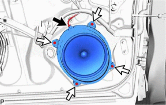
(b) Remove the 4 screws.
|
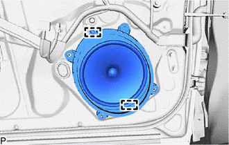
(c) Disengage the 2 guides to remove the front No. 1 speaker assembly. |
|
READ NEXT:
 Inspection
INSPECTION PROCEDURE 1. INSPECT FRONT NO. 1 SPEAKER ASSEMBLY
(a) With the speaker installed, check that there is no looseness or other abnormalities.
(b) Check that there is no foreign matter in t
Installation
INSTALLATION CAUTION / NOTICE / HINT
HINT:
Use the same procedure for the RH side and LH side.
The following procedure is for the LH side.
PROCEDURE 1. INSTALL FRONT NO. 1 SPEAKER ASSEMB
SEE MORE:
Cleaning and protecting
the vehicle interior
The following procedures will help protect your vehicle's interior
and keep it in top condition:
Protecting the vehicle interior
Remove dirt and dust using a vacuum cleaner. Wipe dirty surfaces
with a cloth dampened with lukewarm water.
If dirt cannot be removed, wipe it off with a soft cl
Problem Symptoms Table
PROBLEM SYMPTOMS TABLE
HINT:
Use the table below to help determine the cause of problem symptoms. If multiple suspected areas are listed, the potential causes of the symptoms are listed in order of probability in the "Suspected Area" column of the table. Check each symptom by checking the susp
