Toyota Camry (XV70): Installation
INSTALLATION
CAUTION / NOTICE / HINT
HINT:
- Use the same procedure for the RH side and LH side.
- The following procedure is for the LH side.
PROCEDURE
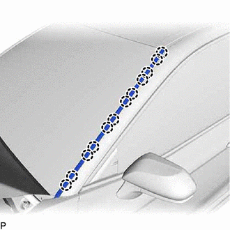
1. INSTALL NO. 3 WINDSHIELD OUTSIDE MOULDING CLIP
HINT:
Perform the following procedure only when replacement of a No. 3 windshield outside moulding clip is necessary.
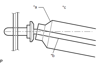
(a) Using a riveter with a nose piece, install 6 new No. 3 windshield outside moulding clips.
HINT:
If the mandrel of the No. 3 windshield outside moulding clip does not come off on the first operation of the rivet gun, slide the rivet gun forward on the mandrel and operate it again.
NOTICE:
- Do not pry the No. 3 windshield outside moulding clip with the riveter, as this will cause damage to the riveter and mandrel.
- Confirm that the No. 3 windshield outside moulding clips are seated properly against the vehicle body.
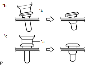
*a
Riveter
*b
Incorrect
*c
Correct
- Do not tilt the riveter when installing the No. 3 windshield outside moulding clip to the vehicle body.
|
*a | Riveter |
|
*b | Mandrel |
|
*c | Incorrect |
(b) Install the windshield glass sub-assembly.
Click here .gif)
2. INSTALL NO. 1 WINDSHIELD OUTSIDE MOULDING CLIP
HINT:
Perform the following procedure only when replacement of a No. 1 windshield outside moulding clip is necessary.
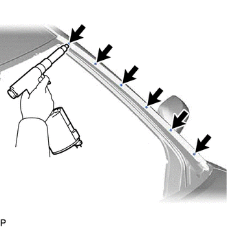
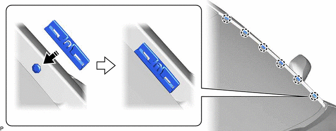
(a) Engage the 6 claws to install the 6 No. 1 windshield outside moulding clips as shown in the illustration.
.png) |
Install in this Direction |
- | - |
3. INSTALL WINDSHIELD OUTSIDE MOULDING
| (a) Engage the 12 claws to install the windshield outside moulding. |
|
4. INSTALL FRONT FENDER TO COWL SIDE SEAL
Click here
READ NEXT:
 Horn
Horn
ComponentsCOMPONENTS ILLUSTRATION
*1 COOL AIR INTAKE DUCT SEAL
*2 HIGH PITCHED HORN ASSEMBLY
*3 LOW PITCHED HORN ASSEMBLY
- -
N*m (kgf*cm,
SEE MORE:
Installation
INSTALLATION CAUTION / NOTICE / HINT
HINT:
Use the same procedure for the RH side and LH side.
The following procedure is for the LH side.
PROCEDURE 1. INSTALL REAR DOOR WINDOW FRAME MOULDING SUB-ASSEMBLY
(a) Engage the guide, 2 claws and clip to temporarily install the rear do
Components
COMPONENTS ILLUSTRATION
*A w/o Navigation Antenna
*B w/ Navigation Antenna
*1 ANTENNA CORD SUB-ASSEMBLY
*2 INSTRUMENT PANEL SAFETY PAD SUB-ASSEMBLY
*3 NO. 2 SIDE DEFROSTER NOZZLE DUCT
*4 NO. 3 HEATER TO REGISTER DUCT SUB-ASSEMBLY ILLUSTRATIO
