
Toyota Camry (XV70): Horn
Components
COMPONENTS
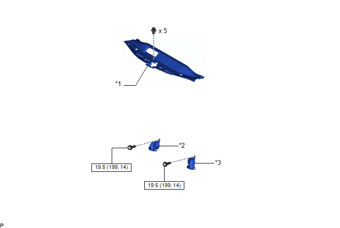
ILLUSTRATION
|
*1 | COOL AIR INTAKE DUCT SEAL |
*2 | HIGH PITCHED HORN ASSEMBLY |
|
*3 | LOW PITCHED HORN ASSEMBLY |
- | - |
.png) |
N*m (kgf*cm, ft.*lbf): Specified torque |
- | - |
Removal
REMOVAL
PROCEDURE
1. REMOVE COOL AIR INTAKE DUCT SEAL
Click here
.gif)
2. REMOVE HIGH PITCHED HORN ASSEMBLY
| (a) Remove the bolt. |
|
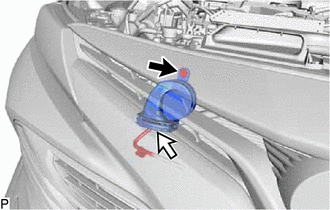
(b) Disconnect the connector to remove the high pitched horn assembly.
3. REMOVE LOW PITCHED HORN ASSEMBLY
| (a) Remove the bolt. |
|
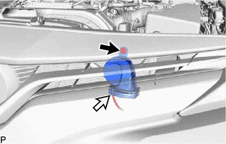
(b) Disconnect the connector to remove the low pitched horn assembly.
Inspection
INSPECTION
PROCEDURE
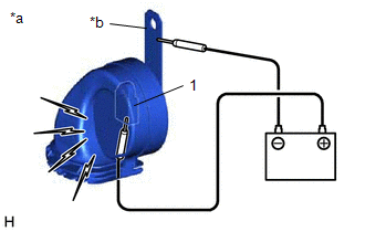
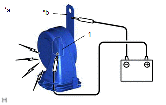
1. INSPECT HIGH PITCHED HORN ASSEMBLY
| (a) Apply battery voltage and check the operation of the high pitched horn assembly according to the table below. OK:
If the result is not as specified, replace the high pitched horn assembly. |
|
2. INSPECT LOW PITCHED HORN ASSEMBLY
| (a) Apply battery voltage and check the operation of the low pitched horn assembly according to the table below. OK:
If the result is not as specified, replace the low pitched horn assembly. |
|
Installation
INSTALLATION
PROCEDURE
1. INSTALL LOW PITCHED HORN ASSEMBLY
(a) Connect the connector.
(b) Install the low pitched horn assembly with the bolt.
Torque:
19.5 N
READ NEXT:
 Precaution
PRECAUTION PRECAUTION FOR DISCONNECTING CABLE FROM NEGATIVE BATTERY TERMINAL
NOTICE: When disconnecting the cable from the negative (-) battery terminal, initialize the following systems after the
Parts Location
PARTS LOCATION ILLUSTRATION
*A for Type A
*B for Type B
*1 HIGH PITCHED HORN ASSEMBLY
*2 LOW PITCHED HORN ASSEMBLY
*3 HORN RELAY
*4 ENGI
SEE MORE:
Removal
REMOVAL PROCEDURE 1. REMOVE V-BANK COVER SUB-ASSEMBLY
Click here
2. REMOVE CAMSHAFT TIMING OIL CONTROL SOLENOID ASSEMBLY (for Exhaust Side of Bank 2)
(a) Disconnect the camshaft timing oil control solenoid assembly connector.
(b) Remove the 2 bolts and camsha
Engine Difficult to Start
DESCRIPTION
Problem Symptom Suspected Area
Trouble Area
Engine speed fluctuation due to abnormal combustion
Idle speed too low or high
Strong engine vibration due to above symptoms
Ignition malfunction
Deviation in air fuel ratio (Excessive or i
