Toyota Camry (XV70): Parts Location
Toyota Camry Repair Manual XV70 (2018-2024) / Vehicle Exterior / Horn / Horn System / Parts Location
PARTS LOCATION
ILLUSTRATION
|
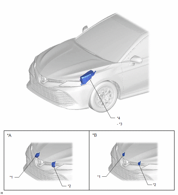
*A | for Type A |
*B | for Type B |
|
*1 | HIGH PITCHED HORN ASSEMBLY |
*2 | LOW PITCHED HORN ASSEMBLY |
|
*3 | HORN RELAY |
*4 | ENGINE ROOM RELAY BLOCK - HORN FUSE |
ILLUSTRATION
|
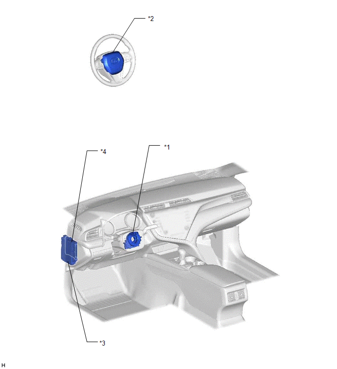
*1 | SPIRAL CABLE SUB-ASSEMBLY |
*2 | HORN BUTTON ASSEMBLY |
|
*3 | INSTRUMENT PANEL JUNCTION BLOCK ASSEMBLY |
*4 | MAIN BODY ECU (MULTIPLEX NETWORK BODY ECU) |
READ NEXT:
 System Diagram
SYSTEM DIAGRAM
Problem Symptoms Table
PROBLEM SYMPTOMS TABLE NOTICE: Before replacing the main body ECU (multiplex network body ECU), refer to Registration.*
Click here
*: w/ Smart Key System
HINT: Use the table b
Data List / Active Test
DATA LIST / ACTIVE TEST ACTIVE TEST HINT:
Using the Techstream to perform Active Tests allows relays, VSVs, actuators and other items to be operated without removing any parts. This non-intrusive f
SEE MORE:
Right Rear Wheel Speed Sensor Internal Electronic Failure (C051249)
DESCRIPTION When the system is starting up and the skid control ECU (brake actuator assembly) detects a speed sensor circuit malfunction via the speed sensor circuit self-diagnosis function, this DTC is stored.
DTC No. Detection Item
DTC Detection Condition Trouble Area
C05124
Driving the vehicle
The following procedures should be observed to ensure safe
driving:
Driving
1. With the brake pedal depressed, shift the shift lever to D.
2. Release the parking brake.
3. Gradually release the brake pedal and gently depress the accelerator
pedal to accelerate the vehicle.
Stopping
1. With t
© 2023-2026 Copyright www.tocamry.com
