
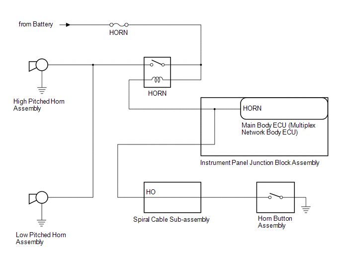
Toyota Camry (XV70): System Diagram
Toyota Camry Repair Manual XV70 (2018-2024) / Vehicle Exterior / Horn / Horn System / System Diagram
SYSTEM DIAGRAM
READ NEXT:
 Problem Symptoms Table
PROBLEM SYMPTOMS TABLE NOTICE: Before replacing the main body ECU (multiplex network body ECU), refer to Registration.*
Click here
*: w/ Smart Key System
HINT: Use the table b
Data List / Active Test
DATA LIST / ACTIVE TEST ACTIVE TEST HINT:
Using the Techstream to perform Active Tests allows relays, VSVs, actuators and other items to be operated without removing any parts. This non-intrusive f
Relay
On-vehicle InspectionON-VEHICLE INSPECTION PROCEDURE
1. INSPECT HORN RELAY
*a Component without harness connected (HORN Relay)
(a) Measure the resistance according to the valu
SEE MORE:
Installation
INSTALLATION CAUTION / NOTICE / HINT
HINT:
Use the same procedure for the RH side and LH side.
The following procedure is for the LH side.
PROCEDURE 1. INSTALL SIDE TURN SIGNAL LIGHT ASSEMBLY
(a) for Type A: (1) Connect the connector. (2) Engage the 2 guides.
(3) Engage the
Antenna Cord
ComponentsCOMPONENTS ILLUSTRATION
*1 ANTENNA CORD SUB-ASSEMBLY
*2 INSTRUMENT PANEL SAFETY PAD SUB-ASSEMBLY
*3 NO. 2 SIDE DEFROSTER NOZZLE DUCT
*4 NO. 3 HEATER TO REGISTER DUCT SUB-ASSEMBLY RemovalREMOVAL CAUTION / NOTICE / HINT
The necessary procedures (adj
© 2023-2026 Copyright www.tocamry.com
