Toyota Camry (XV70): Terminals Of Ecu
TERMINALS OF ECU
CHECK ECM (for A25A-FKS)
HINT:
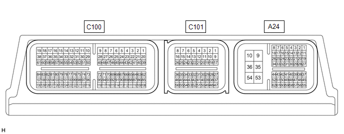
The standard voltage, resistance and waveform between each pair of the ECM terminals is shown in the table below. The appropriate conditions for checking each pair of the terminals is also indicated. The result of checks should be compared with the standard voltage, resistance and waveform for each pair of the terminals as displayed in the Specified Condition column. The illustration above can be used as a reference to identify the ECM terminal locations.
|
Terminal No. (Symbols) | Wiring Color |
Terminal Description | Condition |
Specified Condition |
|---|---|---|---|---|
|
A24-21 (STP) - A24-10 (E1) |
SB - W-B | Stop light switch assembly signal |
Brake pedal depressed |
11 to 14 V |
| Brake pedal released |
Below 1 V | |||
|
A24-22 (ST1-) - A24-10 (E1) |
LG - W-B | Stop light switch assembly signal |
Ignition switch ON, brake pedal depressed |
Below 1 V |
| Ignition switch ON, brake pedal released |
11 to 14 V | |||
|
A24-27 (CCS) - A24-28 (ECCS) |
R - BE | Steering pad switch circuit |
Cruise control switch not pushed |
1 MΩ or higher |
|
Cruise control main switch pushed |
Below 2.5 Ω | |||
|
+RES switch pushed | 235 to 245 Ω | |||
|
-SET switch pushed | 617 to 643 Ω | |||
|
CANCEL switch pushed |
1509 to 1571 Ω |
CHECK ECM (for 2GR-FKS)
HINT:
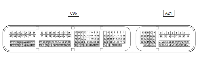
The standard voltage, resistance and waveform between each pair of the ECM terminals is shown in the table below. The appropriate conditions for checking each pair of the terminals is also indicated. The result of checks should be compared with the standard voltage, resistance and waveform for each pair of the terminals as displayed in the Specified Condition column. The illustration above can be used as a reference to identify the ECM terminal locations.
|
Terminal No. (Symbols) | Wiring Color |
Terminal Description | Condition |
Specified Condition |
|---|---|---|---|---|
|
A21-27 (STP) - A96-53 (E1) |
SB - W-B | Stop light switch assembly signal |
Brake pedal depressed |
11 to 14 V |
| Brake pedal released |
Below 1 V | |||
|
A21-41 (CCS) - A96-53 (E1) |
R - W-B | Steering pad switch circuit |
Cruise control switch not pushed |
1 MΩ or higher |
|
Cruise control main switch pushed |
Below 2.5 Ω | |||
|
+RES switch pushed | 235 to 245 Ω | |||
|
-SET switch pushed | 617 to 643 Ω | |||
|
CANCEL switch pushed |
1509 to 1571 Ω | |||
|
A21-42 (ST1-) - A96-53 (E1) |
LG - W-B | Stop light switch assembly signal |
Ignition switch ON, brake pedal depressed |
Below 1 V |
| Ignition switch ON, brake pedal released |
11 to 14 V |
NOTICE:
- DTCs may be output when connectors are disconnected during inspection. Therefore, be sure to clear the DTCs using the Techstream once the inspection has been completed.
- Do not apply excessive force to the forward recognition camera connector.

|
*A | Before Nov. 2021 Production |
*B | From Nov. 2021 Production |
CHECK FORWARD RECOGNITION CAMERA
(a) Measure the voltage and resistance according to the value(s) in the table below.
Before Nov. 2021 Production|
Terminal No. (Symbol) | Wiring Color |
Terminal Description | Condition |
Specified Condition |
|---|---|---|---|---|
|
V6-3 (LKSW) - V6-10 (GND) |
V - W-B | Steering pad switch assembly signal (distance control signal) |
Ignition switch ON, steering pad switch assembly (vehicle-to-vehicle distance control switch) off |
4.75 to 5.25 V |
|
Ignition switch ON, steering pad switch assembly (vehicle-to-vehicle distance control switch) on |
Below 1 V | |||
|
V6-7 (IGB) - V6-10 (GND) |
LA-P - W-B |
Power source | Ignition switch ON |
11 to 14 V |
|
Ignition switch off | Below 1 V | |||
|
V6-10 (GND) - Body ground |
W-B - Body ground | Ground |
Always | Below 1 Ω |
|
Terminal No. (Symbol) | Wiring Color |
Terminal Description | Condition |
Specified Condition |
|---|---|---|---|---|
|
V21-3 (LKSW) - V21-10 (GND) |
V - W-B | Steering pad switch assembly signal (distance control signal) |
Ignition switch ON, steering pad switch assembly (vehicle-to-vehicle distance control switch) off |
4.75 to 5.25 V |
|
Ignition switch ON, steering pad switch assembly (vehicle-to-vehicle distance control switch) on |
Below 1 V | |||
|
V21-7 (IGB) - V21-10 (GND) |
LA-P - W-B |
Power source | Ignition switch ON |
11 to 14 V |
|
Ignition switch off | Below 1 V | |||
|
V21-10 (GND) - Body ground |
W-B - Body ground | Ground |
Always | Below 1 Ω |
READ NEXT:
 Diagnosis System
DIAGNOSIS SYSTEM DIAGNOSIS FUNCTION (a) The diagnosis function turns off the cruise control indicator, illuminates the master warning light and displays a warning message when a malfunction is detecte
Dtc Check / Clear
DTC CHECK / CLEAR NOTICE: When the diagnosis system is changed from normal mode to check mode or vice versa, all DTCs and freeze frame data recorded in normal mode are cleared. Before changing modes,
Freeze Frame Data
FREEZE FRAME DATA CHECK FREEZE FRAME DATA HINT:
The ECU records vehicle and driving condition information as freeze frame data the moment a DTC is stored.
(a) Enter the following menus: Powertrain
SEE MORE:
Wiper and Washer Switch Circuit
DESCRIPTION The condition of the windshield wiper switch assembly is detected and sent to the steering sensor in this circuit. WIRING DIAGRAM
PROCEDURE
1. READ VALUE USING TECHSTREAM
(a) Connect the Techstream to the DLC3. (b) Turn the ignition switch to ON.
(c) Turn the Te
Front Disc Brake Pad
ComponentsCOMPONENTS ILLUSTRATION
*1 FRONT DISC BRAKE ANTI-SQUEAL SHIM KIT
*2 FRONT DISC BRAKE PAD
*3 FRONT DISC BRAKE CYLINDER ASSEMBLY
*4 FRONT DISC BRAKE PAD WEAR INDICATOR PLATE
*5 FRONT NO. 1 DISC BRAKE ANTI-SQUEAL SHIM
*6 FRONT NO. 2 DISC
