Toyota Camry (XV70): Installation
INSTALLATION
CAUTION / NOTICE / HINT
HINT:
- Use the same procedure for the RH side and LH side.
- The following procedure is for the LH side.
PROCEDURE
1. INSTALL REAR DOOR WINDOW FRAME MOULDING SUB-ASSEMBLY
(a) Engage the guide, 2 claws and clip to temporarily install the rear door window frame moulding sub-assembly to the door frame.
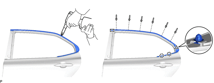
(b) Using an air riveter or hand riveter with a nose piece, install the rear door window frame moulding sub-assembly with 6 new rivets.
HINT:
If the mandrel of the rivet does not come off on the first operation of the rivet gun, slide the rivet gun forward on the mandrel and operate it again.
NOTICE:
- Do not pry the rivet with the riveter, as this will cause damage to the riveter and mandrel.
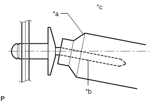
*a
Riveter
*b
Mandrel
*c
Incorrect
- Confirm that the rivets are seated properly against the moulding.
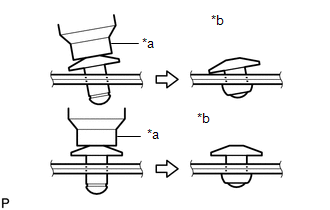
*a
Riveter
*b
Incorrect
- Do not tilt the riveter when installing the rivet to the moulding.
- Do not leave any space between the rivet head and moulding.
- Do not leave any space between the moulding and door frame. Firmly hold the 2 items together while installing the rivet.
.png)
*a
Riveter
*b
Incorrect
2. INSTALL REAR DOOR FRONT WINDOW FRAME MOULDING
HINT:
When installing a new rear door front window frame moulding, heat the vehicle body and rear door front window frame moulding using a heat light.
Heating Temperature|
Item | Temperature |
|---|---|
|
Vehicle Body | 40 to 60 |
READ NEXT:
 Components
COMPONENTS ILLUSTRATION
*A except TRD
*B for TRD
*1 LUGGAGE COMPARTMENT DOOR COVER
*2 REAR SPOILER
*3 REAR SPOILER RETAINER
- -
Removal
REMOVAL PROCEDURE 1. REMOVE LUGGAGE COMPARTMENT DOOR COVER
Click here 2. REMOVE REAR SPOILER
(a) Apply protective tape around the rear spoiler as shown in the illustration.
SEE MORE:
Glass Position Initialization Incomplete (B2313)
DESCRIPTION The power window regulator motor assemblies are operated by the multiplex network master switch assembly, power window regulator switch assembly or rear power window regulator switch assemblies. The power window regulator motor assembly has motor, regulator and ECU functions.
When the
Components
COMPONENTS ILLUSTRATION
*1 FUEL SENDER GAUGE ASSEMBLY
*2 FUEL SUCTION TUBE WITH PUMP AND GAUGE ASSEMBLY
