Toyota Camry (XV70): Brake System Control Module "A" System Voltage System Voltage Low (C137BA2)
DESCRIPTION
If a malfunction is detected in the power supply circuit, the skid control ECU (brake actuator assembly) stores this DTC and the fail-safe function prohibits ABS operation.
This DTC is stored when the +BS terminal voltage meets one of the DTC detection conditions due to a malfunction in the power supply or charging circuit such as the battery or alternator circuit, etc.
The DTC is cleared when the +BS terminal voltage returns to normal.
|
DTC No. | Detection Item |
DTC Detection Condition | Trouble Area |
|---|---|---|---|
|
C137BA2 | Brake System Control Module "A" System Voltage System Voltage Low |
Any of the following is detected:
|
|
*: The skid control ECU (brake actuator assembly) monitors the resistance of the power source line at the +BS terminal. A malfunction is detected when an abnormality occurs in the +BS terminal wire harness or its connection and the skid control ECU (brake actuator assembly) determines that the wiring resistance at the +BS terminal exceeds the standard resistance.
DTC Detection Conditions: C137BA2|
Vehicle Condition | |||||||
|---|---|---|---|---|---|---|---|
|
Pattern 1 | Pattern 2 |
Pattern 3 | Pattern 4 |
Pattern 5 | Pattern 6 | ||
|
Diagnosis Condition | The vehicle speed is 6 km/h (4 mph) or more. |
○ | ○ |
- | - |
- | - |
|
The vehicle speed is 15 km/h (9 mph) or more and the +BS terminal voltage is 9.6 V or more. |
- | - |
- | ○ |
- | - | |
|
The system has started. |
- | - |
- | - |
○ | - | |
|
Malfunction Status | The +BS terminal voltage (soft low voltage) is less than 9.6 V. |
○ | - |
- | - |
- | - |
|
The +BS terminal voltage (hard low voltage) is less than 6.9 V. |
- | ○ |
- | - |
- | - | |
|
The +BS terminal voltage is less than 6.7 V and the skid control ECU (brake actuator assembly) judges that power supply voltage is abnormal. |
- | - |
○ | - |
- | - | |
|
The skid control ECU (brake actuator assembly) turns on more than one valve at the same time within a short period of time and the valve relay supply voltage drop exceeds the threshold.* |
- | - |
- | ○ |
- | - | |
|
The +BS terminal voltage is less than 5 V. |
- | - |
- | - |
○ | - | |
|
The +BS terminal voltage is less than 2.6 V. |
- | - |
- | - |
- | ○ | |
|
Detection Time | 1 second or more. |
1 second or more. | 0.06 seconds or more. |
- | 0.5 seconds or more. |
0.2 seconds or more. | |
|
Number of Trips | 1 trip |
1 trip | 1 trip |
1 trip | 1 trip |
1 trip | |
*: The skid control ECU (brake actuator assembly) monitors the resistance of the power source line at the +BS terminal. A malfunction is detected when an abnormality occurs in the +BS terminal wire harness or its connection and the skid control ECU (brake actuator assembly) determines that the wiring resistance at the +BS terminal exceeds the standard resistance.
HINT:
DTC will be output when conditions for either of the patterns in the table above are met.
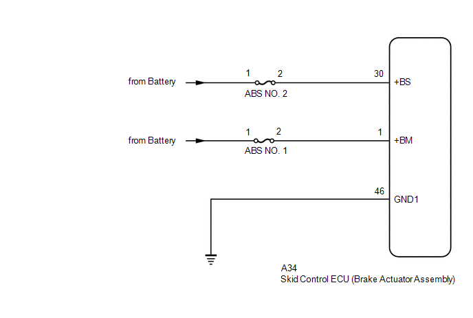
WIRING DIAGRAM
CAUTION / NOTICE / HINT
NOTICE:
- Inspect the fuses for circuits related to this system before performing the following procedure.
- After replacing the skid control ECU (brake actuator assembly), perform acceleration sensor zero point calibration and system information memorization.
Click here
.gif)
PROCEDURE
|
1. | CHECK BATTERY |
(a) Check the battery voltage.
Standard Voltage:
|
Tester Connection | Condition |
Specified Condition |
|---|---|---|
|
Positive (+) terminal - Negative (-) terminal |
Always | 11 to 14 V |
| NG | .gif) | CHECK OR REPLACE CHARGING SYSTEM COMPONENT OR BATTERY for A25A-FKS: Click here for 2GR-FKS: Click here
|
|
.gif)
| 2. |
CHECK HARNESS AND CONNECTOR (POWER SOURCE TERMINAL) |
| (a) Make sure that there is no looseness at the locking part and the connecting part of the connector. OK: The connector is securely connected. |
|
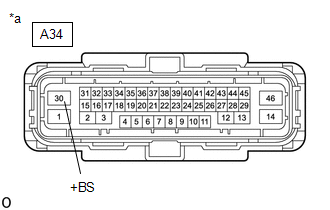
(b) Disconnect the A34 skid control ECU (brake actuator assembly) connector.
(c) Check both the connector case and the terminals for deformation and corrosion.
OK:
No deformation or corrosion.
(d) Measure the voltage according to the value(s) in the table below.
Standard Voltage:
|
Tester Connection | Condition |
Specified Condition |
|---|---|---|
|
A34-30 (+BS) - Body ground |
Always | 11 to 14 V |
| NG | | REPAIR OR REPLACE HARNESS OR CONNECTOR |
|
| 3. |
CHECK HARNESS AND CONNECTOR (POWER SOURCE TERMINAL) |
| (a) Make sure that there is no looseness at the locking part and the connecting part of the connector. OK: The connector is securely connected. |
|
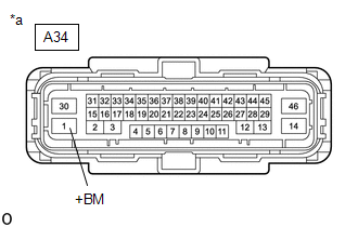
(b) Disconnect the A34 skid control ECU (brake actuator assembly) connector.
(c) Check both the connector case and the terminals for deformation and corrosion.
OK:
No deformation or corrosion.
(d) Measure the voltage according to the value(s) in the table below.
Standard Voltage:
|
Tester Connection | Condition |
Specified Condition |
|---|---|---|
|
A34-1 (+BM) - Body ground |
Always | 11 to 14 V |
| OK | | REPLACE BRAKE ACTUATOR ASSEMBLY |
| NG | | REPAIR OR REPLACE HARNESS OR CONNECTOR |
READ NEXT:
 Brake System Control Module "A" System Voltage System Voltage High (C137BA3)
DESCRIPTION If a malfunction is detected in the power supply circuit, the skid control ECU (brake actuator assembly) stores this DTC and the fail-safe function prohibits ABS operation.
This DTC is s
Stop Lamp Relay Actuator Stuck On (C13807E)
DESCRIPTION When any of the following conditions are met, the skid control ECU (brake actuator assembly) sets the drive output (STPO) ON which operates the stop light control relay (stop light switch
Stop Lamp Relay Actuator Stuck Off (C13807F)
DESCRIPTION Refer to DTC C13807E. Click here
DTC No. Detection Item
DTC Detection Condition Trouble Area
C13807F Stop Lamp Relay Actuator Stuck Off
When the voltage
SEE MORE:
Lost Communication with ECM / PCM "A" (U0100,U0125,U0126,U0129,U0142)
DESCRIPTION These DTCs are stored if there is a malfunction in the CAN communication system connected to the blind spot monitor sensor.
HINT: If CAN communication system DTCs are stored, they may also be stored for other systems. Blind Spot Monitor Master
DTC No. Detection Item
DTC De
Cargo and luggage
Take notice of the following information about storage precautions,
cargo capacity and load:
Capacity and distribution
Cargo capacity depends on the total weight of the occupants.
(Cargo capacity) = (Total load capacity) - (Total weight of occupants)
Steps for Determining Correct Load Limit -
