Toyota Camry (XV70): Components
Toyota Camry Repair Manual XV70 (2018-2024) / Suspension / Rear Suspension / Rear Upper Arm / Components
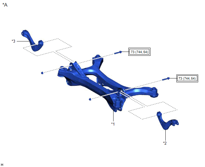
COMPONENTS
ILLUSTRATION
|
*A | for 2WD |
- | - |
|
*1 | REAR SUSPENSION MEMBER SUB-ASSEMBLY |
*2 | REAR UPPER CONTROL ARM ASSEMBLY LH |
|
*3 | REAR UPPER CONTROL ARM ASSEMBLY RH |
- | - |
.png) |
Tightening torque for "Major areas involving basic vehicle performance such as moving/turning/stopping": N*m (kgf*cm, ft.*lbf) |
- | - |
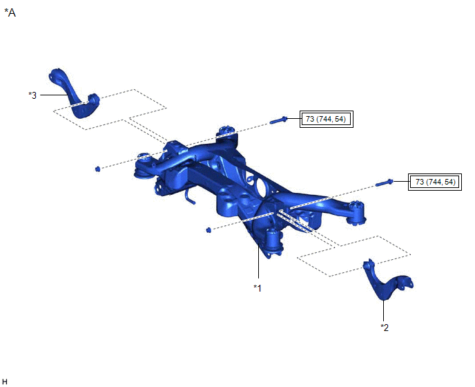
ILLUSTRATION
|
*A | for AWD |
- | - |
|
*1 | REAR SUSPENSION MEMBER SUB-ASSEMBLY |
*2 | REAR UPPER CONTROL ARM ASSEMBLY LH |
|
*3 | REAR UPPER CONTROL ARM ASSEMBLY RH |
- | - |
|
|
Tightening torque for "Major areas involving basic vehicle performance such as moving/turning/stopping": N*m (kgf*cm, ft.*lbf) |
- | - |
READ NEXT:
 Removal
REMOVAL CAUTION / NOTICE / HINT
The necessary procedures (adjustment, calibration, initialization, or registration) that must be performed after parts are removed and installed, or replaced during r
Installation
INSTALLATION PROCEDURE 1. INSTALL REAR UPPER CONTROL ARM ASSEMBLY LH (for 2WD)
(a) Temporarily install the rear upper control arm assembly LH to the rear suspension member sub-assembly with the
SEE MORE:
Replacement
REPLACEMENT CAUTION / NOTICE / HINT
The necessary procedures (adjustment, calibration, initialization or registration) that must be performed after parts are removed and installed, or replaced during transfer case oil seal RH removal/installation are shown below. Necessary Procedures After Parts R
Data List / Active Test
DATA LIST / ACTIVE TEST NOTICE: In the table below, the values listed under "Normal Condition" are reference values. Do not depend solely on these reference values when deciding whether a part is faulty or not.
HINT: Using the Techstream to read the Data List allows the values or states of switche
© 2023-2026 Copyright www.tocamry.com
