
Toyota Camry (XV70): Reassembly
REASSEMBLY
PROCEDURE
1. INSTALL NO. 1 ROOF WIRE (for Normal Roof)
(a) Apply butyl tape as shown in the illustration.
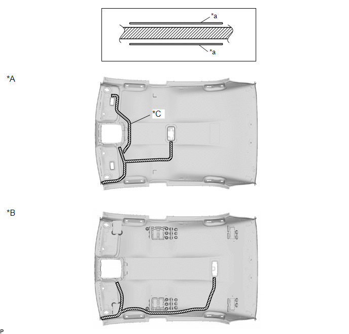
|
*A | w/ Room Light Assembly |
*B | w/ Spot Light Assembly |
|
*C | w/ Vanity Light |
- | - |
|
*a | Marking |
- | - |
.png) |
Butyl Tape | - |
- |
NOTICE:
Securely attach the butyl tape.
(b) Align the marking tape on the No. 1 roof wire with the tab on the front side of the roof headlining.
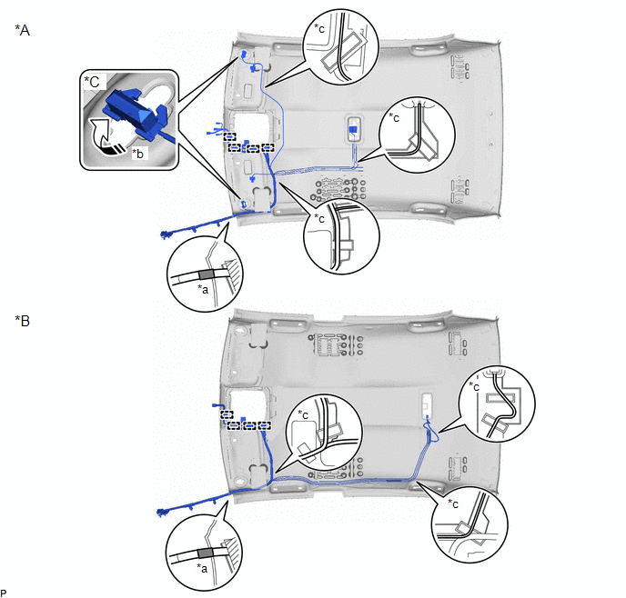
|
*A | w/ Room Light Assembly |
*B | w/ Spot Light Assembly |
|
*C | w/ Vanity Light |
- | - |
|
*a | Marking Tape |
*b | 90° |
|
*c | Adjustment Area |
- | - |
(c) Engage the 4 clamps.
(d) w/ Vanity Light:
(1) Turn the 2 visor connectors clockwise approximately 90° to install them to the roof headlining.
(e) Attach the No. 1 roof wire with the butyl tape.
NOTICE:
- Securely attach the No. 1 roof wire.
- If any of the No. 1 roof wire is left loose, it will cause an abnormal noise.
- Make sure to attach the No. 1 roof wire without leaving any of it loose.
HINT:
Secure the extra length of the No. 1 roof wire in the adjustment area.
(f) Install the No. 1 roof wire to the roof headlining with adhesive tape.
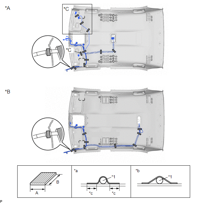
|
*A | w/ Room Light Assembly |
*B | w/ Spot Light Assembly |
|
*C | w/ Vanity Light |
- | - |
|
*1 | No. 1 Roof Wire |
- | - |
|
*a | Correct |
*b | Incorrect |
|
*c | 10 mm (0.394 in.) or more |
- | - |
|
|
Adhesive Tape | - |
- |
|
Area | Dimension |
Area | Dimension |
|---|---|---|---|
|
A | 20 mm (0.787 in.) |
B | 80 mm (3.15 in.) or more |
NOTICE:
- Apply the tape securely in place.
- Do not touch the adhesive surface when applying the tape to prevent adhesion failure.
2. INSTALL NO. 1 ROOF WIRE (for Except Normal Roof)
(a) Apply butyl tape as shown in the illustration.
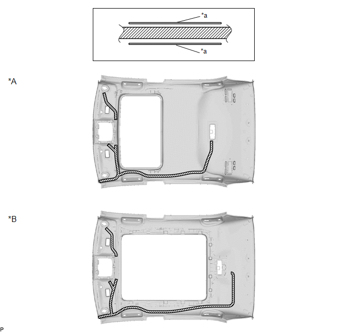
|
*A | for Moon Roof |
*B | for Panoramic Moon Roof |
|
*a | Marking |
- | - |
|
|
Butyl Tape | - |
- |
NOTICE:
Securely attach the butyl tape.
(b) Align the marking tape on the No. 1 roof wire with the tab on the front side of the roof headlining.
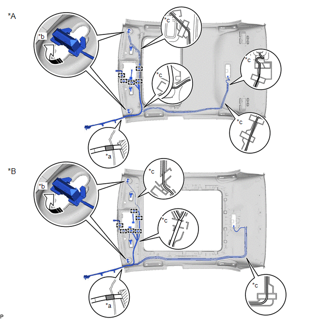
|
*A | for Moon Roof |
*B | for Panoramic Moon Roof |
|
*a | Marking Tape |
*b | 90° |
|
*c | Adjustment Area |
- | - |
.png) |
Rotation Direction | - |
- |
(1) Engage each clamp.
(2) Turn the 2 visor connectors clockwise approximately 90° to install them to the roof headlining.
(3) Attach the No. 1 roof wire with the butyl tape.
NOTICE:
- Securely attach the No. 1 roof wire.
- If any of the No. 1 roof wire is left loose, it will cause an abnormal noise.
- Make sure to attach the No. 1 roof wire without leaving any of it loose.
HINT:
Secure the extra length of the No. 1 roof wire in the adjustment area.
(c) Install the No. 1 roof wire to the roof headlining with adhesive tape.
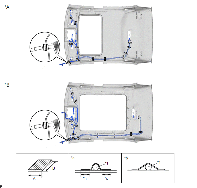
|
*A | for Moon Roof |
*B | for Panoramic Moon Roof |
|
*1 | No. 1 Roof Wire |
- | - |
|
*a | Correct |
*b | Incorrect |
|
*c | 10 mm (0.394 in.) or more |
- | - |
|
|
Adhesive Tape | - |
- |
|
Area | Dimension |
Area | Dimension |
|---|---|---|---|
|
A | 20 mm (0.787 in.) |
B | 80 mm (3.15 in.) or more |
NOTICE:
- Apply the tape securely in place.
- Do not touch the adhesive surface when applying the tape to prevent adhesion failure.
3. INSTALL NO. 2 ANTENNA CORD SUB-ASSEMBLY
Click here
.gif)
4. INSTALL NO. 4 ROOF SILENCER (for Normal Roof)
(a) Align the No. 4 roof silencer with the markings on the roof headlining and install it using hot-melt glue as shown in the illustration.
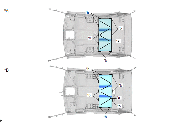
|
*A | w/ Room Light Assembly |
*B | w/ Spot Light Assembly |
|
*a | Hot-melt Glue |
*b | Marking |
5. INSTALL NO. 2 ROOF SILENCER (for Normal Roof)
(a) Align the No. 2 roof silencer with the markings on the roof headlining and install it using hot-melt glue as shown in the illustration.
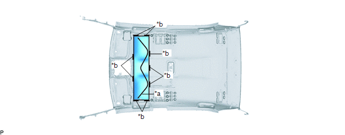
|
*a | Hot-melt Glue |
*b | Marking |
READ NEXT:
SEE MORE:
 Problem Symptoms Table
PROBLEM SYMPTOMS TABLE
HINT:
Use the table below to help determine the cause of problem symptoms. If multiple suspected areas are listed, the potential causes of the symptoms are listed in order of probability in the "Suspected Area" column of the table. Check each symptom by checking the susp
Right Rear Wheel Speed Sensor Signal Stuck Low (C051223)
DESCRIPTION Refer to DTC C051212 Click here
DTC No. Detection Item
DTC Detection Condition Trouble Area
C051223 Right Rear Wheel Speed Sensor Signal Stuck Low
When the vehicle is driven from 0 km/h to 12 km/h (0 mph to 7 mph), the wheel speed is 1.8 km/h (1.1
