
Toyota Camry (XV70): Ambient Light
Components
COMPONENTS
ILLUSTRATION
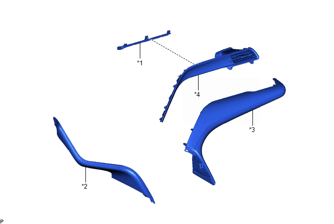
|
*1 | INSTRUMENT PANEL LIGHT ASSEMBLY |
*2 | NO. 1 METER HOOD CLUSTER |
|
*3 | NO. 2 INSTRUMENT PANEL GARNISH SUB-ASSEMBLY |
*4 | NO. 3 INSTRUMENT PANEL REGISTER ASSEMBLY |
Removal
REMOVAL
PROCEDURE
1. REMOVE NO. 1 METER HOOD CLUSTER
Click here
.gif)
2. REMOVE NO. 2 INSTRUMENT PANEL GARNISH SUB-ASSEMBLY
Click here
3. REMOVE NO. 3 INSTRUMENT PANEL REGISTER ASSEMBLY
Click here
4. REMOVE INSTRUMENT PANEL LIGHT ASSEMBLY
| (a) Disengage the 3 claws. |
|
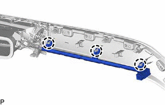
(b) Disengage the 3 guides as shown in the illustration to remove the instrument panel light assembly.
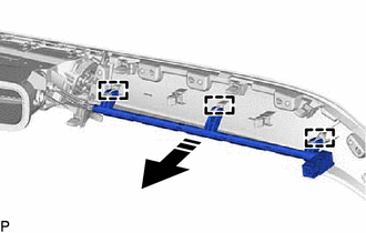
.png) |
Remove in this Direction |
Inspection
INSPECTION
PROCEDURE
1. INSPECT INSTRUMENT PANEL AMBIENT ILLUMINATION LIGHT (INSTRUMENT PANEL LIGHT ASSEMBLY)
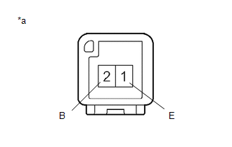
|
*a | Component without harness connected (Instrument Panel Ambient Illumination Light (Instrument Panel Light Assembly)) |
(a) Apply battery voltage to the connector and check that the instrument panel ambient illumination light comes on.
OK:
|
Measurement Condition | Condition |
Specified Condition |
|---|---|---|
|
Battery positive (+) > 2 (B) Battery negative (-) > 1 (E) |
Always | Instrument panel ambient illumination light comes on |
If the result is not as specified, replace the instrument panel ambient illumination light (instrument panel light assembly).
Installation
INSTALLATION
PROCEDURE
1. INSTALL INSTRUMENT PANEL LIGHT ASSEMBLY
(a) Engage the 3 guides as shown in the illustration.
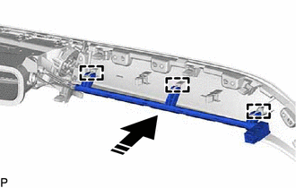
.png) |
Install in this Direction |
(b) Engage the 3 claws to install the instrument panel light assembly.
2. INSTALL NO. 3 INSTRUMENT PANEL REGISTER ASSEMBLY
Click here
.gif)
3. INSTALL NO. 2 INSTRUMENT PANEL GARNISH SUB-ASSEMBLY
Click here
4. INSTALL NO. 1 METER HOOD CLUSTER
Click here
READ NEXT:
SEE MORE:
 Lost Communication with Meter (B1324,B1325)
DESCRIPTION These DTCs are stored when communication between the radio and display receiver assembly and combination meter assembly or headup display (meter mirror sub-assembly)* is not possible.
DTC No. Detection Item
DTC Detection Condition Trouble Area
B1324 Lost Communic
Crankshaft Position - Camshaft Position Correlation Bank 1 Sensor B (P001700,P001900)
DESCRIPTION In the VVT (Variable Valve Timing) system, the appropriate exhaust valve open and close timing is controlled by the ECM. The ECM performs exhaust valve control by performing the following: 1) controlling the exhaust camshaft cam timing oil control solenoid assembly, camshaft timing gear
