
Toyota Camry (XV70): Back Door Courtesy Switch
Components
COMPONENTS
ILLUSTRATION
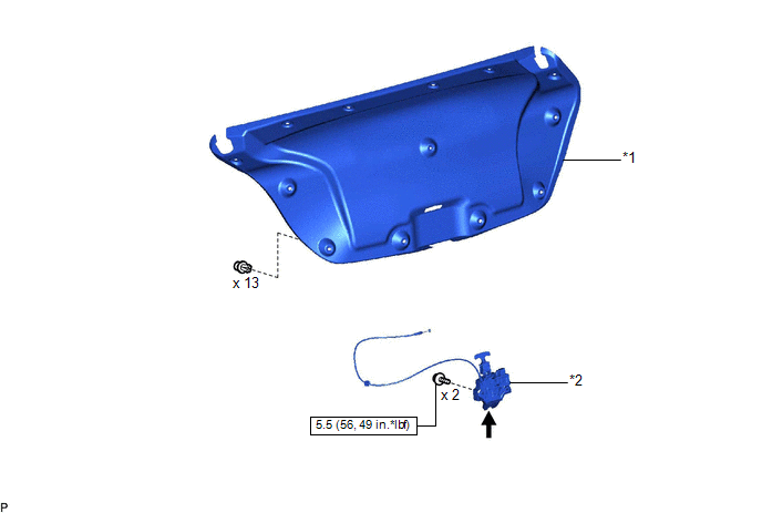
|
*1 | LUGGAGE COMPARTMENT DOOR COVER |
*2 | LUGGAGE COMPARTMENT DOOR LOCK ASSEMBLY |
 |
N*m (kgf*cm, ft.*lbf): Specified torque |
 |
MP Grease |
Removal
REMOVAL
PROCEDURE
1. REMOVE LUGGAGE COMPARTMENT DOOR COVER
Click here

2. REMOVE LUGGAGE COMPARTMENT DOOR LOCK ASSEMBLY
Click here
Inspection
INSPECTION
PROCEDURE
1. INSPECT LUGGAGE COMPARTMENT DOOR COURTESY LIGHT SWITCH (LUGGAGE COMPARTMENT DOOR LOCK ASSEMBLY)
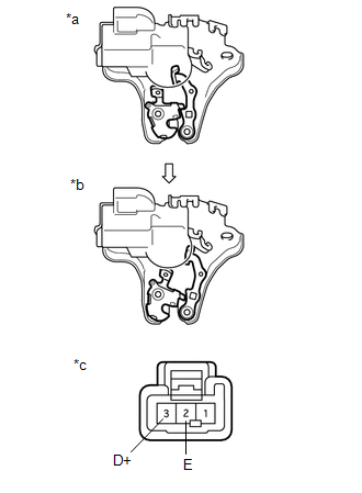
|
*a | Lock |
|
*b | Unlock |
|
*c | Component without harness connected (Luggage Compartment Door Courtesy Light Switch (Luggage Compartment Door Lock Assembly)) |
(a) Inspect the luggage compartment door courtesy switch.
(1) Measure the resistance according to the value(s) in the table below.
Standard Resistance:
|
Tester Connection | Condition |
Specified Condition |
|---|---|---|
|
2 (E) - 3 (D+) | Lock |
10 k? or higher |
|
2 (E) - 3 (D+) | Unlock |
Below 1 ? |
If the result is not as specified, replace the luggage compartment door courtesy light switch (luggage compartment door lock assembly).
Installation
INSTALLATION
PROCEDURE
1. INSTALL LUGGAGE COMPARTMENT DOOR LOCK ASSEMBLY
Click here

2. INSTALL LUGGAGE COMPARTMENT DOOR COVER
Click here
READ NEXT:
 Door Courtesy Light
ComponentsCOMPONENTS ILLUSTRATION
*1 COURTESY LIGHT ASSEMBLY
*2 COURTESY LIGHT BULB
*3 COURTESY LIGHT LENS
*4 COURTESY LIGHT COVER
*5 COURTESY LIGHT HOUSING
Door Courtesy Light Bulb
ReplacementREPLACEMENT CAUTION / NOTICE / HINT
HINT:
Use the same procedure for the RH side and LH side.
The following procedure is for the LH side.
PROCEDURE 1. REMOVE COURTESY LIGHT ASSEMBLY
Footwell Light
ComponentsCOMPONENTS ILLUSTRATION
*A for Driver Side
*B for Front Passenger Side
*1 NO. 1 INSTRUMENT PANEL UNDER COVER SUB-ASSEMBLY
*2 NO. 1 INTERIOR ILLUMINATION LIGHT
SEE MORE:
Driving Adjustment
DRIVING ADJUSTMENT CAUTION / NOTICE / HINT
CAUTION: Radiofrequency radiation exposure information:
This equipment complies with FCC radiation exposure limits set forth for an uncontrolled environment.
This equipment should be kept with minimum distance of 20 cm (7.87 in.) between the rad
Installation
INSTALLATION PROCEDURE 1. INSTALL SLIDING ROOF HOUSING ASSEMBLY
(a) Pass a string under the windshield outside moulding as shown in the illustration.
*1 Windshield Outside Moulding
- -
*a String
- -
(b) Engage the 2 guides.
(c) Temporarily ins
