
Toyota Camry (XV70): Door Courtesy Light
Components
COMPONENTS
ILLUSTRATION
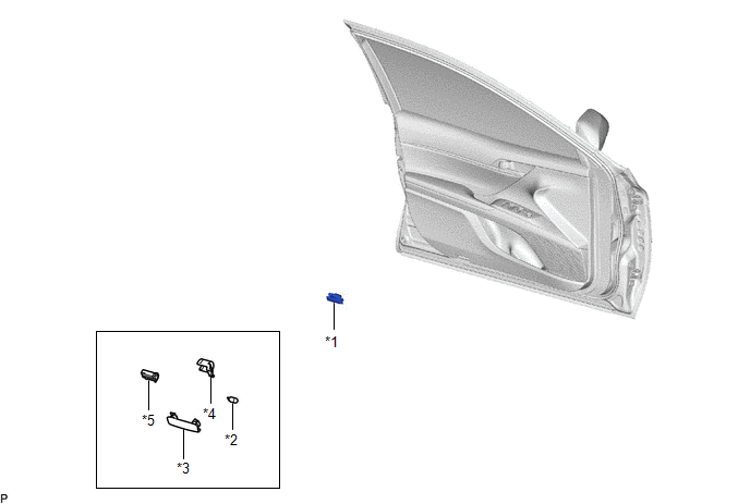
|
*1 | COURTESY LIGHT ASSEMBLY |
*2 | COURTESY LIGHT BULB |
|
*3 | COURTESY LIGHT LENS |
*4 | COURTESY LIGHT COVER |
|
*5 | COURTESY LIGHT HOUSING |
- | - |
Removal
REMOVAL
CAUTION / NOTICE / HINT
HINT:
- Use the same procedure for the RH side and LH side.
- The following procedure is for the LH side.
PROCEDURE
1. REMOVE COURTESY LIGHT ASSEMBLY
| (a) Using a screwdriver with its tip wrapped with protective tape, disengage the claw. |
|
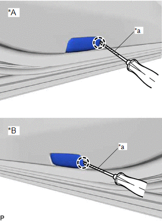
(b) Disconnect the connector to remove the courtesy light assembly.
2. REMOVE COURTESY LIGHT BULB
(a) Using a screwdriver with its tip wrapped with protective tape, disengage the claw and remove the courtesy light housing with the courtesy light cover as shown in the illustration.
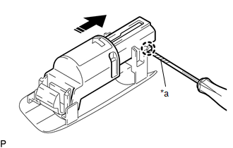
|
*a | Protective Tape |
.png) |
Remove in this Direction |
(b) Remove the courtesy light cover from the courtesy light housing as shown in the illustration.
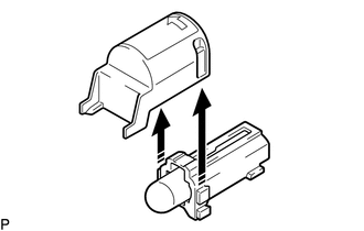
|
|
Remove in this Direction |
(c) Remove the courtesy light bulb from the courtesy light housing as shown in the illustration.
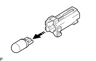
|
|
Remove in this Direction |
Inspection
INSPECTION
PROCEDURE
1. INSPECT COURTESY LIGHT ASSEMBLY
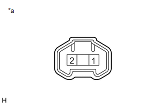
|
*a | Component without harness connected (Courtesy Light Assembly) |
(a) Apply battery voltage to the connector and check that the courtesy light comes on.
OK:
|
Measurement Condition | Condition |
Specified Condition |
|---|---|---|
|
Battery positive (+) > 1 Battery negative (-) > 2 |
Always | Courtesy light comes on |
If the result is not as specified, replace the bulb or courtesy light assembly.
Installation
INSTALLATION
CAUTION / NOTICE / HINT
HINT:
- Use the same procedure for the RH side and LH side.
- The following procedure is for the LH side.
PROCEDURE
1. INSTALL COURTESY LIGHT BULB
(a) Install the courtesy light bulb to the courtesy light housing as shown in the illustration.
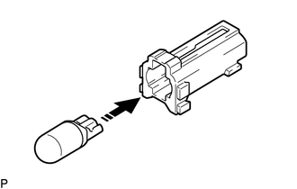
.png) |
Install in this Direction |
(b) Install the courtesy light cover to the courtesy light housing as shown in the illustration.
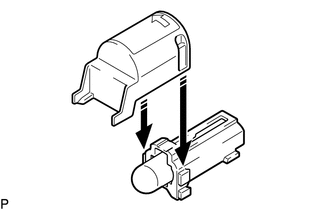
|
|
Install in this Direction |
(c) Engage the claw to install the courtesy light housing with the courtesy light cover as shown in the illustration.
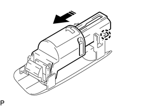
|
|
Install in this Direction |
2. INSTALL COURTESY LIGHT ASSEMBLY
(a) Connect the connector.
| (b) Engage the claw to install the courtesy light assembly. |
|
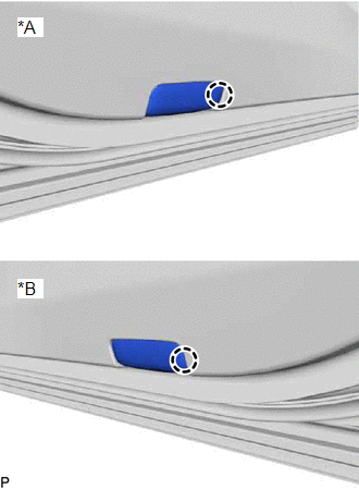
READ NEXT:
SEE MORE:
 Installation
INSTALLATION PROCEDURE 1. INSTALL CHECK VALVE GROMMET
(a) Install a new check valve grommet to the brake booster assembly. 2. INSTALL VACUUM WARNING SWITCH ASSEMBLY
(a) Install the vacuum warning switch assembly to the brake booster assembly as shown in the illustration.
*a 30
Components
COMPONENTS ILLUSTRATION
*1 FRONT FLOOR COVER LH
*2 FRONT FLOOR COVER RH
N*m (kgf*cm, ft.*lbf): Specified torque
- - ILLUSTRATION
*1 BODY MOUNTING PLATE
*2 CENTER FLOOR CROSSMEMBER BRACE
*3 FRONT CENTER FLOOR BRACE
-
