
Toyota Camry (XV70): Footwell Light
Components
COMPONENTS
ILLUSTRATION
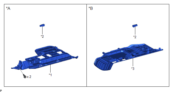
|
*A | for Driver Side |
*B | for Front Passenger Side |
|
*1 | NO. 1 INSTRUMENT PANEL UNDER COVER SUB-ASSEMBLY |
*2 | NO. 1 INTERIOR ILLUMINATION LIGHT ASSEMBLY |
|
*3 | NO. 2 INSTRUMENT PANEL UNDER COVER SUB-ASSEMBLY |
- | - |
Removal
REMOVAL
PROCEDURE
1. REMOVE NO. 1 INSTRUMENT PANEL UNDER COVER SUB-ASSEMBLY (for Driver Side)
Click here .gif)
2. REMOVE NO. 1 INTERIOR ILLUMINATION LIGHT ASSEMBLY (for Driver Side)
| (a) Disengage the 2 claws to remove the No. 1 interior illumination light assembly. |
|
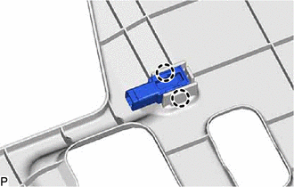
3. REMOVE NO. 2 INSTRUMENT PANEL UNDER COVER SUB-ASSEMBLY (for Front Passenger Side)
Click here
4. REMOVE NO. 1 INTERIOR ILLUMINATION LIGHT ASSEMBLY (for Front Passenger Side)
| (a) Disengage the 2 claws to remove the No. 1 interior illumination light assembly. |
|
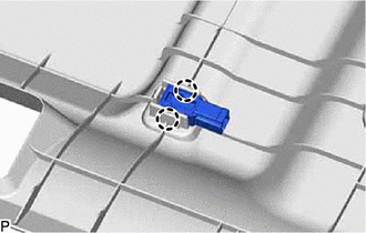
Inspection
INSPECTION
PROCEDURE
1. INSPECT FOOTWELL LIGHT LH (NO. 1 INTERIOR ILLUMINATION LIGHT ASSEMBLY)
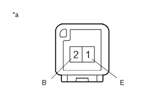
|
*a | Component without harness connected (Footwell Light LH (No. 1 Interior Illumination Light Assembly)) |
(a) Apply battery voltage to the connector and check that the footwell light LH comes on.
OK:
|
Measurement Condition | Condition |
Specified Condition |
|---|---|---|
|
Battery positive (+) > 2 (B) Battery negative (-) > 1 (E) |
Always | Footwell light LH comes on |
If the result is not as specified, replace the footwell light LH (No. 1 interior illumination light assembly).
2. INSPECT FOOTWELL LIGHT RH (NO. 1 INTERIOR ILLUMINATION LIGHT ASSEMBLY)
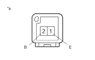
|
*a | Component without harness connected (Footwell Light RH (No. 1 Interior Illumination Light Assembly)) |
(a) Apply battery voltage to the connector and check that the footwell light RH comes on.
OK:
|
Measurement Condition | Condition |
Specified Condition |
|---|---|---|
|
Battery positive (+) > 2 (B) Battery negative (-) > 1 (E) |
Always | Footwell light RH comes on |
If the result is not as specified, replace the footwell light RH (No. 1 interior illumination light assembly).
Installation
INSTALLATION
PROCEDURE
1. INSTALL NO. 1 INTERIOR ILLUMINATION LIGHT ASSEMBLY (for Driver Side)
(a) Engage the 2 claws to install the No. 1 interior illumination light assembly.
2. INSTALL NO. 1 INSTRUMENT PANEL UNDER COVER SUB-ASSEMBLY (for Driver Side)
Click here .gif)
3. INSTALL NO. 1 INTERIOR ILLUMINATION LIGHT ASSEMBLY (for Front Passenger Side)
(a) Engage the 2 claws to install the No. 1 interior illumination light assembly.
4. INSTALL NO. 2 INSTRUMENT PANEL UNDER COVER SUB-ASSEMBLY (for Front Passenger Side)
Click here
READ NEXT:
SEE MORE:
 Hazard Warning Switch
ComponentsCOMPONENTS ILLUSTRATION
*A for 7 Inch Display
*B for 9 Inch Display
*1 CENTER INSTRUMENT CLUSTER FINISH PANEL ASSEMBLY
*2 CENTER INSTRUMENT CLUSTER FINISH PANEL SUB-ASSEMBLY
*3 HAZARD WARNING SIGNAL SWITCH ASSEMBLY
- - Remo
Removal
REMOVAL CAUTION / NOTICE / HINT
The necessary procedures (adjustment, calibration, initialization, or registration) that must be performed after parts are removed and installed, or replaced during rear trailing arm assembly removal/installation are shown below. Necessary Procedures After Parts Rem
