
Toyota Camry (XV70): Removal
REMOVAL
CAUTION / NOTICE / HINT
The necessary procedures (adjustment, calibration, initialization, or registration) that must be performed after parts are removed and installed, or replaced during cooler condenser assembly removal/installation are shown below.
Necessary Procedure After Parts Removed/Installed/Replaced|
Replaced Part or Performed Procedure |
Necessary Procedure | Effect/Inoperative Function when Necessary Procedure not Performed |
Link |
|---|---|---|---|
| Front bumper assembly (w/ Panoramic view monitor system) |
Front television camera view adjustment |
Panoramic view monitor system |
|
PROCEDURE
1. RECOVER REFRIGERANT FROM REFRIGERATION SYSTEM
Click here
.gif)
2. REMOVE HEADLIGHT ASSEMBLY LH
Click here
3. REMOVE HEADLIGHT ASSEMBLY RH
HINT:
Use the same procedure as for the LH side.
4. REMOVE NO. 2 FRONT BUMPER ENERGY ABSORBER
Click here
5. REMOVE FRONT BUMPER ENERGY ABSORBER
Click here
6. REMOVE FRONT BUMPER REINFORCEMENT
Click here
7. REMOVE UPPER RADIATOR MOUNTING BRACKET
for A25A-FKS:
Click here
for 2GR-FKS:
Click here
8. REMOVE INLET AIR CLEANER ASSEMBLY
for A25A-FKS:
Click here
for 2GR-FKS:
Click here
9. REMOVE HOOD LOCK ASSEMBLY
Click here
10. REMOVE NO. 1 RADIATOR AIR GUIDE LH
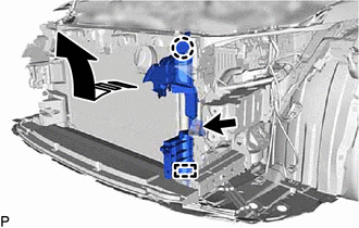
(a) Remove the clip.
.png) |
Remove in this Direction |
(b) Disengage the claw and guide, and remove the No. 1 radiator air guide LH as shown in the illustration.
11. REMOVE FRONT RADIATOR SIDE AIR GUIDE PLATE RH
Click here
12. REMOVE NO. 1 RADIATOR AIR GUIDE RH
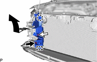
(a) Disconnect the connector.
|
|
Remove in this Direction |
(b) Remove the clip.
(c) Disengage the claw and guide, and remove the No. 1 radiator air guide RH as shown in the illustration.
13. DISCONNECT NO. 1 COOLER REFRIGERANT DISCHARGE HOSE SUB-ASSEMBLY
| (a) Remove the bolt and disconnect the No. 1 cooler refrigerant discharge hose sub-assembly from the cooler condenser assembly. |
|
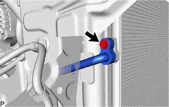
(b) Remove the O-ring from the No. 1 cooler refrigerant discharge hose sub-assembly.
NOTICE:
Seal the openings of the disconnected parts using vinyl tape to prevent entry of moisture and foreign matter.
14. DISCONNECT AIR CONDITIONING TUBE AND ACCESSORY ASSEMBLY
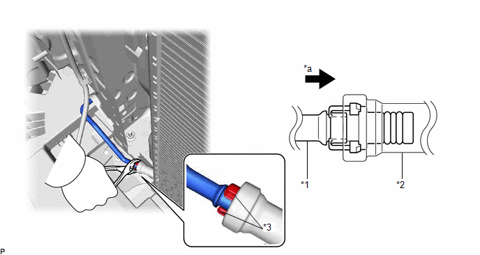
(a) While pressing the end of the air conditioning tube and accessory assembly into the end of the cooler condenser assembly, use pliers to squeeze together both sides of the piping clamp until it breaks apart.
|
*1 | Air Conditioning Tube and Accessory Assembly |
*2 | Cooler Condenser Assembly |
|
*3 | Piping Clamp |
- | - |
|
*a | Press In |
- | - |
NOTICE:
- If any foreign matter is adhered to the connecting part, brush it off or use compressed air to remove it.
- Make sure that fragments of the piping clamp do not enter the piping.
(b) Disconnect the air conditioning tube and accessory assembly.
NOTICE:
Remove any foreign matter from the connecting parts of the air conditioning tube and accessory assembly and cooler condenser assembly.
(c) Remove the 2 O-rings from the air conditioning tube and accessory assembly.
NOTICE:
Wrap the open ends of the separated cooler condenser assembly and air conditioning tube and accessory assembly with vinyl tape to prevent entry of moisture and foreign matter.
(d) Remove the piping clamp.
15. REMOVE UPPER RADIATOR SUPPORT SUB-ASSEMBLY
for A25A-FKS:
Click here
for 2GR-FKS:
Click here
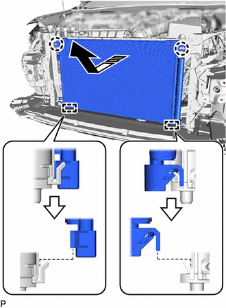
16. REMOVE COOLER CONDENSER ASSEMBLY
(a) Disengage the 2 claws and 2 guides, and remove the cooler condenser assembly as shown in the illustration.
|
|
Remove in this Direction |
NOTICE:
Do not damage the cooler condenser assembly or radiator assembly when removing the cooler condenser assembly.
READ NEXT:
SEE MORE:
 Rear Power Window RH Auto Up / Down Function does not Operate with Rear Power Window Switch RH
DESCRIPTION If the manual up and down functions operate normally but the auto up and down functions do not, the power window control system may be in fail-safe mode.
If power window initialization has not been performed, the auto up and down functions will not operate.
Click here WIRING DIAG
Diagnostic Trouble Code Chart
DIAGNOSTIC TROUBLE CODE CHART Charging System
DTC No. Detection Item
Warning Indicate Memory
Note Link
P161A87 Lost Communication with Alternator Missing Message
Charge warning is not displayed
DTC stored SAE Code: P161A
