Toyota Camry (XV70): Relay
On-vehicle Inspection
ON-VEHICLE INSPECTION
PROCEDURE
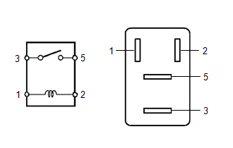
1. INSPECT NO. 1 ELECTRONIC FUEL INJECTION MAIN RELAY (EFI-MAIN NO. 1)
| (a) Measure the resistance according to the value(s) in the table below. Standard Resistance:
If the result is not as specified, replace the No. 1 electronic fuel injection main relay (EFI-MAIN NO. 1). |
|
2. INSPECT NO. 2 ELECTRONIC FUEL INJECTION MAIN RELAY (EFI-MAIN NO. 2)
| (a) Measure the resistance according to the value(s) in the table below. Standard Resistance:
If the result is not as specified, replace the No. 2 electronic fuel injection main relay (EFI-MAIN NO. 2). |
|
3. INSPECT AIR FUEL RATIO SENSOR HEATER RELAY (EFI-MAIN NO. 3)
| (a) Measure the resistance according to the value(s) in the table below. Standard Resistance:
If the result is not as specified, replace the air fuel ratio sensor heater relay (EFI-MAIN NO. 3). |
|
4. INSPECT EFI INJECTION RELAY (D INJ)
| (a) Measure the resistance according to the value(s) in the table below. Standard Resistance:
If the result is not as specified, replace the EFI injector relay (D INJ). |
|
5. INSPECT NO. 2 IGNITION RELAY (IG2 NO. 1)
| (a) Measure the resistance according to the value(s) in the table below. Standard Resistance:
If the result is not as specified, replace the No. 2 ignition relay (IG2 NO. 1). |
|
READ NEXT:
 Precaution
PRECAUTION INITIALIZATION
NOTICE:
Before replacing the ECM, refer to Registration.
Click here
Perform Registration (VIN registration) after replacing the ECM.
Click here
Perform L
Definition Of Terms
DEFINITION OF TERMS
Term Definition
Monitor Description Description of what the ECM monitors and how it detects malfunctions (monitoring purpose and details).
Related DTCs
SEE MORE:
Operation Check
OPERATION CHECK CHECK TIRE PRESSURE WARNING SYSTEM FUNCTION
(a) Using the Data List, check that the current tire pressure is normal.
Click here
(1) Slowly reduce the tire pressure of the front or rear tires and check that the tire pressure on the Data List changes.
(2) Further reduce
Parts Location
PARTS LOCATION ILLUSTRATION
*1 FUEL SENDER GAUGE ASSEMBLY
*2 FUEL PUMP (for Low Pressure)
*3 FUEL PUMP CONTROL ECU
*4 FUEL TANK ASSEMBLY
*5 FUEL SUCTION TUBE WITH PUMP AND GAUGE ASSEMBLY
*6 FUEL MAIN VALVE ASSEMBLY (for Low Pressure)
*7
