Toyota Camry (XV70): Removal
REMOVAL
CAUTION / NOTICE / HINT
NOTICE:
- Immediately after installing the brake pads, the braking performance may be reduced. Always perform a road test in a safe place while paying attention to the surroundings.
- After replacing the front disc brake pads, the brake pedal may feel soft due to clearance between the front disc brake pads and front disc. Depress the brake pedal several times until the brake pedal feels firm.
- After replacing the front disc brake pads, always perform a road test to check the braking performance and check for vibrations.
HINT:
- Use the same procedure for the RH side and LH side.
- The following procedure is for the LH side.
PROCEDURE
1. REMOVE FRONT WHEEL
Click here .gif)
2. REMOVE FRONT DISC BRAKE PAD
CAUTION:
- Be careful not to get pinched by the front disc brake cylinder assembly or other parts when removing the front disc brake pads.
- After lifting up the front disc brake cylinder assembly, secure it in place before performing any work on it.
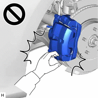
- The front disc brake cylinder assembly could fall, pinching hands or fingers and causing injury.
| (a) Hold the front disc brake cylinder slide pin (lower side) and remove the bolt. NOTICE: Do not kink or damage the brake line. |
|
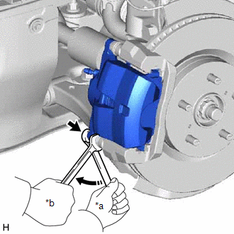
(b) Pull the front disc brake cylinder assembly upward.
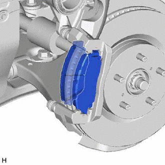
| (c) Remove the 2 front disc brake pads from the front disc brake cylinder mounting. |
|
3. REMOVE FRONT DISC BRAKE ANTI-SQUEAL SHIM KIT
(a) Remove the front No. 1 disc brake anti-squeal shim and front No. 2 disc brake anti-squeal shim from each front disc brake pad.
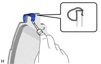
| (b) Using a screwdriver, remove the front disc brake pad wear indicator plate from each front disc brake pad. |
|
READ NEXT:
 Installation
INSTALLATION CAUTION / NOTICE / HINT
NOTICE:
Immediately after installing the brake pads, the braking performance may be reduced. Always perform a road test in a safe place while paying attentio
Components
COMPONENTS ILLUSTRATION
*1 FRONT DISC BRAKE ANTI-SQUEAL SHIM KIT
*2 FRONT DISC BRAKE PAD
*3 FRONT DISC BRAKE CYLINDER ASSEMBLY
*4 FRONT DISC BRAKE PAD WEAR INDICA
SEE MORE:
Data List / Active Test
DATA LIST / ACTIVE TEST DATA LIST HINT:
Using the Techstream to read the Data List allows the values or states of switches, sensors, actuators and other items to be read without removing any parts. This non-intrusive inspection can be very useful because intermittent conditions or signals may be
Brake Vacuum Hose
ComponentsCOMPONENTS ILLUSTRATION
*A for A25A-FKS
- -
*1 NO. 1 VACUUM HOSE CONNECTOR
*2 UNION TO CHECK VALVE HOSE
*3 VACUUM HOSE
*4 CLIP ILLUSTRATION
*A for 2GR-FKS
- -
*1 FRONT CENTER UPPER SUSPENSION BRACE SUB
© 2023-2026 Copyright www.tocamry.com
