Toyota Camry (XV70): Removal
REMOVAL
CAUTION / NOTICE / HINT
The necessary procedures (adjustment, calibration, initialization, or registration) that must be performed after parts are removed and installed, or replaced during roof antenna assembly removal/installation are shown below.
Necessary Procedure After Parts Removed/Installed/Replaced|
Replaced Part or Performed Procedure |
Necessary Procedures | Effect/Inoperative Function when Necessary Procedure not Performed |
Link |
|---|---|---|---|
| Disconnect cable from negative battery terminal |
Perform steering sensor zero point calibration |
Lane Tracing Assist System |
|
|
Pre-collision System | |||
|
Memorize steering angle neutral point |
Parking Assist Monitor System |
| |
|
Panoramic View Monitor System |
|
CAUTION:
Some of these service operations affect the SRS airbag system. Read the precautionary notices concerning the SRS airbag system before servicing.
Click here .gif)
.png)
PROCEDURE
1. REMOVE ROOF HEADLINING ASSEMBLY
Click here
2. REMOVE ROOF ANTENNA ASSEMBLY WITH COVER (except Panoramic Moon Roof)
| (a) Disconnect the connector. |
|
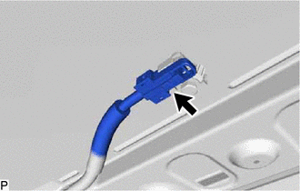
| (b) Remove the bolt. |
|
(c) Pull the washer and holder as shown in the illustration and remove the roof antenna assembly with cover.
.png) |
Remove in this Direction |
3. REMOVE ROOF ANTENNA ASSEMBLY (except Panoramic Moon Roof)
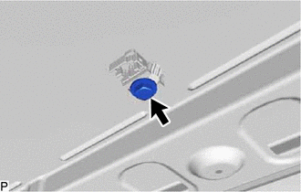
(a) Pull the roof antenna assembly in the direction indicated by the arrow (1) shown in the illustration to disengage the 3 claws and 2 guides.
|
|
Remove in this Direction (1) |
 |
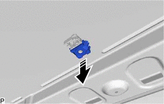
Remove in this Direction (2) |
(b) Pull the roof antenna assembly in the direction indicated by the arrow (2) shown in the illustration to disengage the guide and remove the roof antenna assembly.
(c) When reusing the roof antenna assembly:
| (1) Remove the seal. |
|
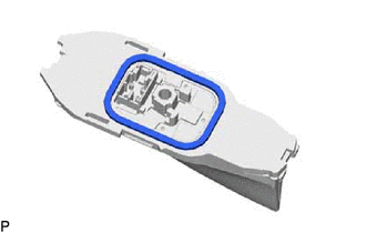
4. REMOVE ROOF ANTENNA ASSEMBLY (for Panoramic Moon Roof)
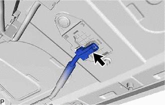
| (a) Disconnect the connector. |
|
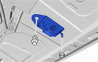
| (b) Remove the nut and clip. |
|
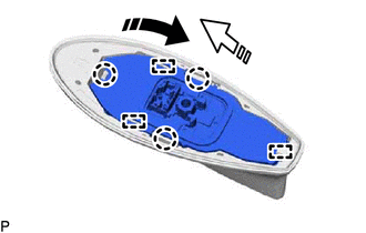
(c) Disengage the 2 claws and remove the roof antenna assembly as shown in the illustration.
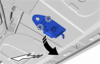
|
|
Remove in this Direction (1) |
|
|
Remove in this Direction (2) |
READ NEXT:
 Installation
INSTALLATION PROCEDURE 1. INSTALL ROOF ANTENNA ASSEMBLY (except Panoramic Moon Roof)
(a) When reusing the roof antenna assembly: (1) Install a new seal.
(b) Push the roof antenna assembly in the d
Components
COMPONENTS ILLUSTRATION
*1 AUDIO AMPLIFIER COVER
*2 STEREO COMPONENT AMPLIFIER ASSEMBLY WITH BRACKET ILLUSTRATION
*1 NO. 1 AMPLIFIER BRACKET
*2 NO. 2 AMPLIFI
SEE MORE:
System Voltage Circuit Short to Ground or Open (P056014)
MONITOR DESCRIPTION The battery supplies electricity to the ECM even when the engine switch is off. This power allows the ECM to store data such as DTC history, freeze frame data and fuel trim values. If the battery voltage falls below a minimum level, the memory is cleared and the ECM determines th
Check Mode Procedure
CHECK MODE PROCEDURE HINT: Compared to normal mode, check mode is more sensitive to malfunctions. Therefore, check mode can detect malfunctions that cannot be detected in normal mode.
NOTICE: All the stored DTCs and freeze frame data are cleared if: 1) the ECM is changed from normal mode to check
