Toyota Camry (XV70): Removal
REMOVAL
CAUTION / NOTICE / HINT
The necessary procedures (adjustment, calibration, initialization, or registration) that must be performed after parts are removed and installed, or replaced during rear No. 1 differential mount cushion removal/installation are shown below.
Necessary Procedures After Parts Removed/Installed/Replaced|
Replaced Part or Performed Procedure |
Necessary Procedure | Effect/Inoperative Function when Necessary Procedure not Performed |
Link |
|---|---|---|---|
| Rear wheel alignment adjustment |
|
|
|
|
Suspension, tires, etc. (The vehicle height changes because of suspension or tire replacement) |
Rear television camera assembly optical axis (Back camera position setting) |
Parking assist monitor system |
|
| Panoramic view monitor system |
| |
|
Exhaust system parts | Inspection after repair |
|
|
CAUTION:
To prevent burns, do not touch the engine, exhaust pipe or other high temperature components while the engine is hot.
PROCEDURE
1. REMOVE REAR DIFFERENTIAL CARRIER ASSEMBLY
Click here
.gif)
2. REMOVE REAR NO. 1 DIFFERENTIAL MOUNT CUSHION
(a) Using SST, remove the rear No. 1 differential mount cushion.
SST: 09316-12010
SST: 09570-24011
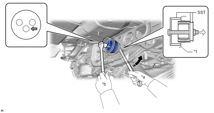
|
*1 | Rear Suspension Member Sub-assembly |
- | - |
|
*a | Turn |
*b | Hold |
 |
Turning Direction |
 |
Front of Vehicle |
 |
SST Bolt Position | - |
- |
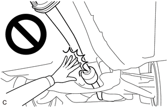
NOTICE:
- Do not bring SST into contact with the rear suspension member sub-assembly.
- Before using SST, apply grease to SST bolt.
- Set SST in the correct direction.
- Do not tilt the SST bolt.
- Do not reuse the rear No. 1 differential mount cushion.
READ NEXT:
 Installation
INSTALLATION PROCEDURE 1. INSTALL REAR NO. 1 DIFFERENTIAL MOUNT CUSHION
(a) Using SST, install a new rear No. 1 differential mount cushion. SST: 09316-12010
SST: 09570-24011
*1 Rear Sus
Differential Oil
ComponentsCOMPONENTS ILLUSTRATION
*1 REAR DIFFERENTIAL FILLER PLUG
*2 REAR DIFFERENTIAL DRAIN PLUG
*3 GASKET
- -
N*m (kgf*cm, ft.*lbf): Specified t
Differential System
PrecautionPRECAUTION
Before disassembling the differential assembly, thoroughly clean it by removing any sand, mud or foreign matter. This will help prevent contamination during disassembly and r
SEE MORE:
Removal
REMOVAL CAUTION / NOTICE / HINT
NOTICE:
Immediately after installing the brake pads, the braking performance may be reduced. Always perform a road test in a safe place while paying attention to the surroundings.
After replacing the rear disc brake pads, the brake pedal may feel soft due t
Terminals Of Ecu
TERMINALS OF ECU
NOTICE:
DTCs may be output when connectors are disconnected during inspection. Therefore, be sure to clear the DTCs using the Techstream once the inspection has been completed.
Do not apply excessive force to the forward recognition camera connector.
*A Be
