Toyota Camry (XV70): Removal
REMOVAL
CAUTION / NOTICE / HINT
The necessary procedures (adjustment, calibration, initialization, or registration) that must be performed after parts are removed and installed, or replaced during rear drive shaft assembly removal/installation are shown below.
Necessary Procedures After Parts Removed/Installed/Replaced|
Replaced Part or Performed Procedure |
Necessary Procedure | Effect/Inoperative Function when Necessary Procedure not Performed |
Link |
|---|---|---|---|
| Rear wheel alignment adjustment |
|
|
|
|
Suspension, tires, etc. (The vehicle height changes because of suspension or tire replacement) |
Rear television camera assembly optical axis (Back camera position setting) |
Parking assist monitor system |
|
| Panoramic view monitor system |
|
HINT:
- Use the same procedure for the RH side and LH side.
- The following procedure is for the LH side.
PROCEDURE
1. REMOVE REAR WHEEL
Click here
.gif)
2. REMOVE REAR AXLE CARRIER
Click here
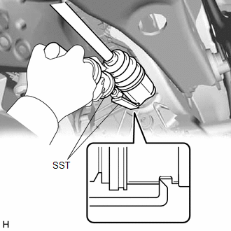
3. REMOVE REAR DRIVE SHAFT ASSEMBLY LH
| (a) Using SST, remove the rear drive shaft assembly LH from the rear differential carrier assembly. SST: 09520-01011 SST: 09520-20010 09521-02010 09521-02040 09521-02060 NOTICE:
|
|
4. REMOVE REAR DRIVE SHAFT INBOARD JOINT SHAFT SNAP RING LH
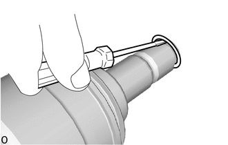
(a) Using a screwdriver, remove the rear drive shaft inboard joint shaft snap ring LH.
READ NEXT:
 Disassembly
DISASSEMBLY CAUTION / NOTICE / HINT
NOTICE:
When using a vise, place aluminum plates between the part and vise.
When using a vise, do not overtighten it.
HINT:
Use the same procedur
Inspection
INSPECTION CAUTION / NOTICE / HINT
NOTICE:
When using a vise, place aluminum plates between the part and vise.
When using a vise, do not overtighten it.
PROCEDURE 1. INSPECT REAR DRIVE S
Reassembly
REASSEMBLY CAUTION / NOTICE / HINT
NOTICE:
When using a vise, place aluminum plates between the part and vise.
When using a vise, do not overtighten it.
HINT:
Use the same procedure
SEE MORE:
Tire information
Typical tire symbols
Full-size tire
Compact spare tire
Tire size
Summer tires or all season tires
An all season tire has "M+S" on the sidewall. A tire not marked "M+S"
is a summer tire.
TUBELESS or TUBE TYPE
A tubeless tire does not have a tube and air is directly put into the
Terminals Of Ecu
TERMINALS OF ECU CHECK MULTIPLEX NETWORK MASTER SWITCH ASSEMBLY
(a) Disconnect the O2 multiplex network master switch assembly connector.
(b) Measure the voltage and resistance according to the value(s) in the table below.
HINT: Measure the values on the wire harness side with the connecto
