Toyota Camry (XV70): Inspection
INSPECTION
CAUTION / NOTICE / HINT
NOTICE:
- When using a vise, place aluminum plates between the part and vise.
- When using a vise, do not overtighten it.
PROCEDURE
1. INSPECT REAR DRIVE SHAFT ASSEMBLY
| (a) Check that there is no excessive play in the radial direction of the outboard joint. |
|
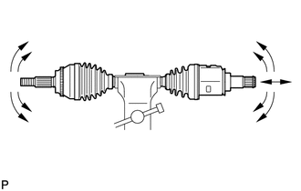
(b) Check that the inboard joint slides smoothly in the thrust direction.
(c) Check that there is no excessive play in the radial direction of the inboard joint.
(d) Check the boots for damage.
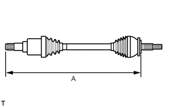
| (e) Check whether the drive shaft dimension (A) is within specification. Length (A): 749.1 to 759.1 mm (2.46 to 2.49 ft.) NOTICE: Keep the drive shaft assembly level during inspection. If the boots are stretched or contracted, correct them. |
|
READ NEXT:
 Reassembly
REASSEMBLY CAUTION / NOTICE / HINT
NOTICE:
When using a vise, place aluminum plates between the part and vise.
When using a vise, do not overtighten it.
HINT:
Use the same procedure
Installation
INSTALLATION CAUTION / NOTICE / HINT
HINT:
Use the same procedure for the RH and LH sides.
The procedure listed below is for the LH side.
PROCEDURE 1. INSTALL REAR DRIVE SHAFT INBOARD JO
SEE MORE:
Problem Symptoms Table
PROBLEM SYMPTOMS TABLE
HINT:
Use the table below to help determine the cause of problem symptoms. If multiple suspected areas are listed, the potential causes of the symptoms are listed in order of probability in the "Suspected Area" column of the table. Check each symptom by checking the s
Removal
REMOVAL CAUTION / NOTICE / HINT
NOTICE:
Immediately after installing the brake pads, the braking performance may be reduced. Always perform a road test in a safe place while paying attention to the surroundings.
After replacing the rear disc brake pads, always perform a road test to check
© 2023-2026 Copyright www.tocamry.com
