
Toyota Camry (XV70): Components
COMPONENTS
ILLUSTRATION
.png)
|
*1 | FRONT FLOOR COVER LH |
*2 | FRONT FLOOR COVER RH |
.png) |
N*m (kgf*cm, ft.*lbf): Specified torque |
- | - |
ILLUSTRATION
|
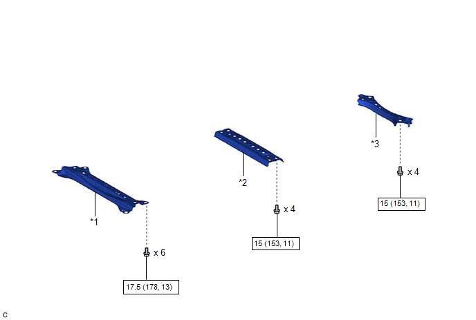
*1 | BODY MOUNTING PLATE |
*2 | CENTER FLOOR CROSSMEMBER BRACE |
|
*3 | FRONT CENTER FLOOR BRACE |
- | - |
|
|
N*m (kgf*cm, ft.*lbf): Specified torque |
- | - |
ILLUSTRATION
|
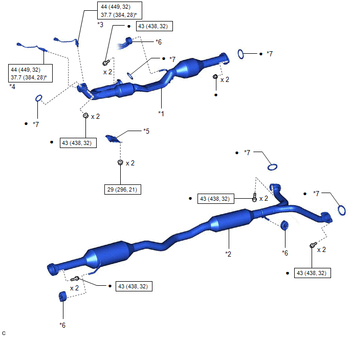
*1 | FRONT EXHAUST PIPE ASSEMBLY (TWC: Rear Catalyst) |
*2 | CENTER EXHAUST PIPE ASSEMBLY |
|
*3 | HEATED OXYGEN SENSOR (for Bank 2) |
*4 | HEATED OXYGEN SENSOR (for Bank 1) |
|
*5 | NO. 1 EXHAUST PIPE SUPPORT BRACKET (for Lower Side) |
*6 | EXHAUST PIPE SUPPORT |
|
*7 | GASKET |
- | - |
|
|
N*m (kgf*cm, ft.*lbf): Specified torque |
* | For use with SST |
|
● | Non-reusable part |
- | - |
ILLUSTRATION
|
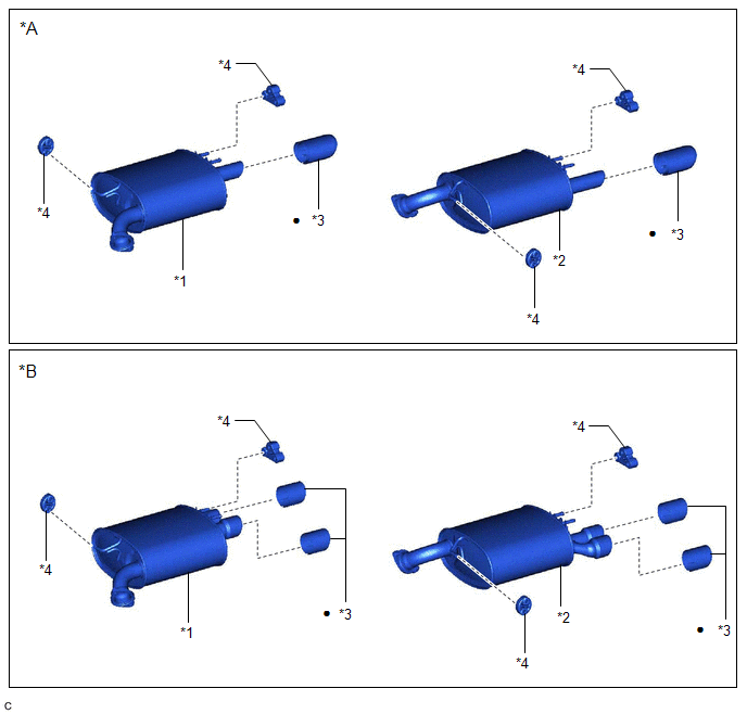
*A | Type A |
*B | Type B |
|
*1 | TAIL EXHAUST PIPE ASSEMBLY |
*2 | TAIL EXHAUST PIPE ASSEMBLY LH |
|
*3 | TAIL EXHAUST PIPE BAFFLE SUB-ASSEMBLY |
*4 | EXHAUST PIPE SUPPORT |
|
● | Non-reusable part |
- | - |
READ NEXT:
 Removal
REMOVAL CAUTION / NOTICE / HINT
The necessary procedures (adjustment, calibration, initialization or registration) that must be performed after parts are removed and installed, or replaced during fr
Installation
INSTALLATION PROCEDURE 1. INSTALL TAIL EXHAUST PIPE BAFFLE SUB-ASSEMBLY
HINT:
Perform this procedure only when replacement of the tail exhaust pipe baffle sub-assembly is necessary.
If the
Components
COMPONENTS ILLUSTRATION
*1 FRONT FLOOR COVER LH
*2 FRONT FLOOR COVER RH
N*m (kgf*cm, ft.*lbf): Specified torque
- - ILLUSTRATION
*1 BODY MOUN
SEE MORE:
Lost Communication with Sliding Sunshade ECU (B2329)
DESCRIPTION This DTC is stored when LIN communication between the roof sunshade ECU (sliding roof drive gear assembly) and main body ECU (multiplex network body ECU) stops for 10 seconds or more.
DTC No. Detection Item
DTC Detection Condition Trouble Area
B2329 Lost Communic
Installation
INSTALLATION CAUTION / NOTICE / HINT
HINT:
Use the same procedure for the RH side and LH side.
The following procedure is for the LH side.
PROCEDURE 1. INSTALL FRONT DRIVE SHAFT HOLE SNAP RING
(a) Install a new front drive shaft hole snap ring. NOTICE: Face the end gap of the front d
© 2023-2026 Copyright www.tocamry.com
