Toyota Camry (XV70): Removal
REMOVAL
CAUTION / NOTICE / HINT
The necessary procedures (adjustment, calibration, initialization or registration) that must be performed after parts are removed and installed, or replaced during front exhaust pipe assembly (TWC: Rear Catalyst), center exhaust pipe assembly and tail exhaust pipe assembly removal/installation are shown below.
Necessary Procedures After Parts Removed/Installed/Replaced|
Replaced Part or Performed Procedure |
Necessary Procedure | Effect/Inoperative Function when Necessary Procedure not Performed |
Link |
|---|---|---|---|
| Inspection After Repair |
|
|
CAUTION:
To prevent burns, do not touch the engine, exhaust pipe or other high temperature components while the engine is hot.
.png)
PROCEDURE
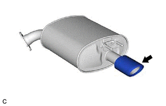
1. REMOVE TAIL EXHAUST PIPE ASSEMBLY
CAUTION:
To prevent burns, do not touch the engine, exhaust pipe or other high temperature components while the engine is hot.
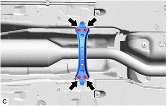
| (a) Remove the 2 bolts and disconnect the tail exhaust pipe assembly from the center exhaust pipe assembly. |
|
(b) Remove the tail exhaust pipe assembly from the 2 exhaust pipe supports.
(c) Remove the gasket from the center exhaust pipe assembly.
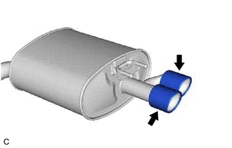
2. REMOVE TAIL EXHAUST PIPE ASSEMBLY LH
CAUTION:
To prevent burns, do not touch the engine, exhaust pipe or other high temperature components while the engine is hot.
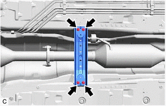
| (a) Remove the 2 bolts and disconnect the tail exhaust pipe assembly LH from the center exhaust pipe assembly. |
|
(b) Remove the tail exhaust pipe assembly LH from the 2 exhaust pipe supports.
(c) Remove the gasket from the center exhaust pipe assembly.
3. REMOVE FRONT FLOOR COVER LH
| (a) Remove the 3 bolts and 4 clips (A). |
|
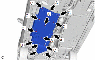
(b) Disengage the grommet (B) and 6 clips (C) to remove the front floor cover LH.
4. REMOVE FRONT FLOOR COVER RH
| (a) Remove the 3 bolts and 4 clips (A). |
|
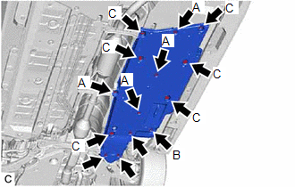
(b) Disengage the grommet (B) and 6 clips (C) to remove the front floor cover RH.
5. REMOVE FRONT CENTER FLOOR BRACE
| (a) Remove the 4 bolts and front center floor brace from the vehicle body. |
|
6. REMOVE CENTER FLOOR CROSSMEMBER BRACE
| (a) Remove the 4 bolts and center floor crossmember brace from the vehicle body. |
|
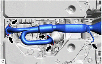
7. REMOVE CENTER EXHAUST PIPE ASSEMBLY
CAUTION:
To prevent burns, do not touch the engine, exhaust pipe or other high temperature components while the engine is hot.
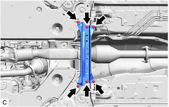
| (a) Remove the 2 bolts, 2 nuts and disconnect the center exhaust pipe assembly from the front exhaust pipe assembly (TWC: Rear Catalyst). |
|
(b) Remove the center exhaust pipe assembly from the 2 exhaust pipe supports.
(c) Remove the gasket from the front exhaust pipe assembly (TWC: Rear Catalyst).
8. REMOVE BODY MOUNTING PLATE
| (a) Remove the 6 bolts and body mounting plate. |
|
9. REMOVE NO. 1 EXHAUST PIPE SUPPORT BRACKET (for Lower Side)
| (a) Remove the 2 nuts and No. 1 exhaust pipe support bracket (for Lower Side). |
|
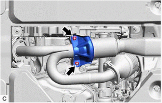
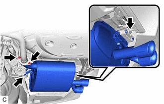
10. REMOVE FRONT EXHAUST PIPE ASSEMBLY (TWC: Rear Catalyst)
CAUTION:
To prevent burns, do not touch the engine, exhaust pipe or other high temperature components while the engine is hot.
| (a) Disconnect the 2 heated oxygen sensor connectors. |
|
.png)
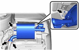
(b) Disengage the 2 wire harness clamps.
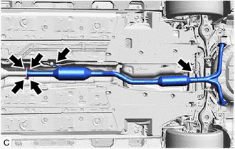
| (c) Remove the 2 bolts, 2 nuts and disconnect the front exhaust pipe assembly (TWC: Rear Catalyst) from the exhaust manifold (TWC: Front Catalyst). |
|
(d) Remove the front exhaust pipe assembly (TWC: Rear Catalyst) from the exhaust pipe support.
(e) Remove the 2 gaskets from the front exhaust pipe assembly (TWC: Rear Catalyst).
11. REMOVE HEATED OXYGEN SENSOR (for Bank 2)
Click here
.gif)
12. REMOVE HEATED OXYGEN SENSOR (for Bank 1)
Click here
13. REMOVE TAIL EXHAUST PIPE BAFFLE SUB-ASSEMBLY
HINT:
- Perform this procedure only when replacement of the tail exhaust pipe baffle sub-assembly is necessary.
- If the tail exhaust pipe baffle sub-assembly is removed, replace it with a new one.
- Use the same procedure as for the tail exhaust pipe assembly LH.
| (a) Type A (1) Remove the tail exhaust pipe baffle sub-assembly. |
|
| (b) Type B (1) Remove the tail exhaust pipe baffle sub-assembly. |
|
READ NEXT:
 Installation
INSTALLATION PROCEDURE 1. INSTALL TAIL EXHAUST PIPE BAFFLE SUB-ASSEMBLY
HINT:
Perform this procedure only when replacement of the tail exhaust pipe baffle sub-assembly is necessary.
If the
Components
COMPONENTS ILLUSTRATION
*1 FRONT FLOOR COVER LH
*2 FRONT FLOOR COVER RH
N*m (kgf*cm, ft.*lbf): Specified torque
- - ILLUSTRATION
*1 BODY MOUN
Removal
REMOVAL CAUTION / NOTICE / HINT
The necessary procedures (adjustment, calibration, initialization or registration) that must be performed after parts are removed and installed, or replaced during fr
SEE MORE:
Reassembly
REASSEMBLY PROCEDURE 1. INSTALL FUEL PUMP
HINT: Perform "Inspection After Repair" after replacing the fuel pump.
Click here
(a) Apply gasoline to a new O-ring. Then install the O-ring and fuel pump spacer to the fuel pump.
*1 O-ring
*2 Fu
RCTA function - RCTA (Rear Cross Traffic
Alert)
The RCTA functions when your vehicle is in reverse. It can detect
other vehicles approaching from the right or left rear of the vehicle. It
uses radar sensors to alert the driver of the other vehicle's existence
through flashing the outside rear view mirror indicators and sounding
a buzzer.
